Check patentability & draft patents in minutes with Patsnap Eureka AI!

Methods and apparatus for laser cleaning of fabric materials

a technology of fabric materials and apparatus, applied in the direction of laser beam fibre treatment, physical treatment, manufacturing tools, etc., can solve the problems of requiring subsequent drying, high water and power consumption of machines, and affecting the cleaning effect of fabrics

Active Publication Date: 2019-05-07
WOODROW SCI LTD
View PDF53 Cites 0 Cited by
  • Summary
  • Abstract
  • Description
  • Claims
  • Application Information

AI Technical Summary

Benefits of technology

This method significantly reduces water, steam, and electrical power usage while effectively removing contaminants from substrates, allowing for efficient and environmentally friendly cleaning of a wide range of materials, including fabrics, without the need for extensive drying processes.

Problems solved by technology

Such machines have a high consumption of both water and power, with an average domestic washing machine using between 9-10 liters of water and consuming approximately 0.75 KW-hour electricity per wash load.
Once the items are cleaned, the very nature of the cleaning process leaves the articles quite wet and requires subsequent drying, either in an inefficient machine such as a commercial tumble drier or through inefficient use of a building's heating system (radiators, etc.) or through outside drying via direct sunlight and / or wind.
Dry cleaning processes typically involve extensive use of hydrocarbon solvents such as perchloroethylene, and the storage, treatment and disposal of such chemicals may pose environment concerns.
Furthermore, dry-cleaning equipment is specialist and is often extremely expensive and non-portable.
In a household setting, the use of a washing machine to clean such items on a daily basis can be excessive, and can result in a degradation in the lifetime of the article due to the mechanical nature of the cleaning process and the need, very often, for drying of the garment in direct sunlight.

Method used


Image

  • Methods and apparatus for laser cleaning of fabric materials
  • Methods and apparatus for laser cleaning of fabric materials
  • Methods and apparatus for laser cleaning of fabric materials

Examples


Embodiment Construction

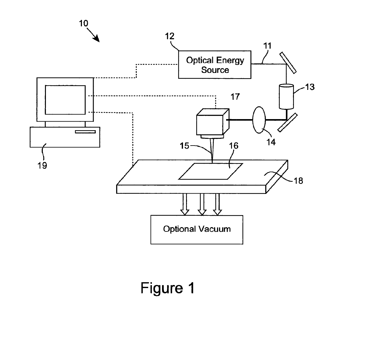
[0063]FIG. 1 illustrates one embodiment of an apparatus 10 for laser cleaning of a substrate, such as, for example, a practical fabric material. The apparatus 10 comprises an optical transmission pathway arranged for propagating optical energy received from source of optical radiation for emanation of the optical energy for the cleaning of the substrate, and which in the embodiment of FIG. 1 can comprise a beam expander, focussing lens and scanning head. For example, the optical output beam 11 from the source of optical energy, which preferably comprises laser source 12, is beam shaped using a beam expander 13 and focussing lens 14 into a focussed beam 15 at the surface of a substrate 16. The beam can be scanned over the substrate surface using a laser beam scan head 17 and the substrate can be scanned with respect to the focussed beam using an x-y or x-y-z axes translation stage 18. Typically the laser, scan head and translation stage are controlled by a computer 19 to determine th...


PUM

PropertyMeasurementUnit
wavelengthaaaaaaaaaa

Abstract

Disclosed are methods and apparatus for cleaning a substrate, such as a fabric material, involving the application of optical energy to the substrate, typically in the form of a beam of light, where the energy of the beam causes removal of the contaminant from substrate, such as from the fibers of a fabric material. The cleaning may occur via any mechanism, including one or more of, alone or in any combination, ablation, melting, heating or reaction with the substrate or contaminant or agent introduced to aid in the cleaning. The optical energy is typically applied to a selected area of the substrate (e.g., as a beam), and the substrate and beam or optical energy source moved relative to one another so as to clean a larger area of the substrate, either by moving the substrate or the beam, or both. Movement of the beam with respect to the substrate can be attained through a beam scanning mechanism or through movement of the optical source itself.

Description

FIELD OF THE INVENTION[0001]The present invention relates to an apparatus and methods of cleaning substrates using optical energy. More particularly, the invention is concerned with using optical energy to clean fabric materials.BACKGROUND[0002]Conventional cleaning apparatus and processes typically utilise an aqueous method or a method which utilises chemicals. Consider, for example, household washing machines or dry cleaning, which is more commonly used within industrial cleaning processes.[0003]Domestic cleaning of clothes or other fabric articles typically involves hand washing processes or more commonly front or top-loaded drum-style washing machines which employ both an aqueous and mechanical cleaning process, often requiring detergents and stain removal chemicals. Such machines have a high consumption of both water and power, with an average domestic washing machine using between 9-10 liters of water and consuming approximately 0.75 KW-hour electricity per wash load. Once the...

Claims


Application Information

Patent Timeline
Patent Type & Authority Patents(United States)
IPC IPC(8): B08B7/00B23K26/0622D06L4/00B23K26/354B23K26/352D06F75/14B23K26/03B23K26/06B23K26/00D06F75/00D06F75/02D06F75/08D06F75/22D06M10/00D06F75/20B23K26/073B23K26/082B23K101/34B23K103/00
CPCD06M10/005B23K26/0006B23K26/0096B23K26/032B23K26/0622B23K26/0648B23K26/0738B23K26/082B23K26/352B23K26/354D06F75/00D06F75/02D06F75/08D06F75/14D06F75/20D06F75/22D06L4/00B08B7/0042B23K2103/50B23K2101/34B23K2103/38B23K2103/40B23K2103/42
Inventor CLOWES, JOHN REDVERS
Owner WOODROW SCI LTD
Features
  • R&D
  • Intellectual Property
  • Life Sciences
  • Materials
  • Tech Scout
  • Unparalleled Data Quality
  • Higher Quality Content
  • 60% Fewer Hallucinations
Learn More