Unlock instant, AI-driven research and patent intelligence for your innovation.

Electronic device and method for dynamically controlling current of an electronic device

a technology of electronic devices and current control, applied in the direction of liquid/fluent solid measurement, instruments, transportation and packaging, etc., can solve the problems of reducing the operational efficiency of the electronic device, consuming power, and charging the external device, so as to reduce the amount of current provided

Active Publication Date: 2019-06-04
QUANTA COMPUTER INC
View PDF11 Cites 0 Cited by
  • Summary
  • Abstract
  • Description
  • Claims
  • Application Information

AI Technical Summary

Benefits of technology

This method enhances operational efficiency by ensuring high-efficiency devices receive sufficient power, reducing the need for frequency adjustments and improving system stability and user experience.

Problems solved by technology

Therefore, for the electronic device, charging the external device is a major factor affecting power consumption and operational efficiency.
Therefore, when the electronic device is connected to too many external devices, too much power will be consumed, reducing the operational efficiency of the electronic device.

Method used


Image

  • Electronic device and method for dynamically controlling current of an electronic device
  • Electronic device and method for dynamically controlling current of an electronic device
  • Electronic device and method for dynamically controlling current of an electronic device

Examples


first embodiment

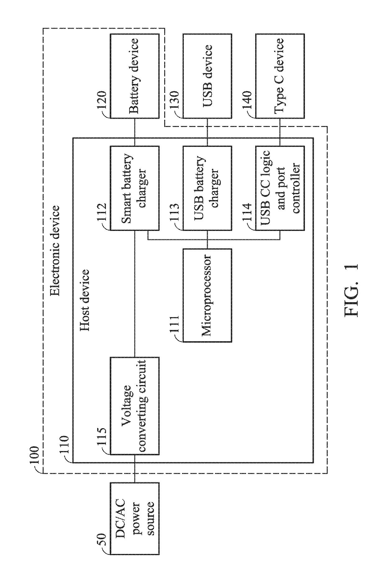
[0034]According to the invention, the device controller may be a battery controller for controlling the battery device 120, such as the smart battery charger 112 shown in FIG. 1. When the device controller is the smart battery charger 112 for controlling the battery device 120, the setting value is the amount of charging current required by the battery device 120. Generally, the microprocessor 111 reads the information regarding the amount of charging current required by the battery device 120 from the battery device 120 and provides the information to the smart battery charger 112. The microprocessor 111 may read information regarding the amount of charging current required by the battery device 120 from the parameters carried by the battery device 120 on the bus.

[0035]As to the actual charging current of the battery device (that is, the actual charging current that is eventually provided to the battery device), it is determined based on the function Min{the charging current requir...

second embodiment

[0042]According to the invention, the device controller may be an external device controller for controlling the external device coupled or connected to the electronic device via the input / output port, such as the USB battery charger 113 or the USB CC logic and port controller 114 as shown in FIG. 1. When the device controller is the USB battery charger 113 or the USB CC logic and port controller 114, the setting value may be a port type or a current mode.

[0043]Generally, the port type or the current mode of an external device is selected based on the charging / power mode of the electronic device. Therefore, in the conventional design, when the charging / power mode of the electronic device is not changed, the port type or the current mode of the external device will not be changed.

[0044]However, according to the second embodiment of the invention, when the microprocessor 111 determines that the amount of power consumption is greater than the threshold, the microprocessor 111 may instr...


PUM


Abstract

An electronic device includes a device controller and a microprocessor. The device controller is coupled to a device for controlling the device. The microprocessor is coupled to the device controller. The microprocessor obtains information regarding an amount of power consumption of the electronic device and dynamically determines an amount of current provided to the device according to the amount of power consumption. When the microprocessor determines that the amount of power consumption is greater than a threshold, the microprocessor determines to decrease the amount of current provided to the device.

Description

CROSS REFERENCE TO RELATED APPLICATIONS[0001]This Application claims priority of Taiwan Patent Application No. 105137782, filed on Nov. 18, 2016, the entirety of which is incorporated by reference herein.BACKGROUND OF THE INVENTIONField of the Invention[0002]The invention relates to a dynamic current control method, which is capable of dynamically controlling the amount of current drawn by a low-efficiency device and improving the operational efficiency of an electronic device system.Description of the Related Art[0003]Electronic devices such as notebook computers have multiple input / output interfaces of different types for connecting external devices. In addition to communicating with the electronic device, an external device connected to the electronic device usually receives power from the electronic device via the input / output interface. Therefore, for the electronic device, charging the external device is a major factor affecting power consumption and operational efficiency.[00...

Claims


Application Information

Patent Timeline
Patent Type & Authority Patents(United States)
IPC IPC(8): H02J7/00G06F1/26
CPCH02J7/007G06F1/266H02J7/0054H02J2007/0062H02J2007/006G06F1/3212G06F1/3296G06F1/263H02J7/342H02J2207/30H02J7/00
Inventor YU, CHUN-JIE
Owner QUANTA COMPUTER INC