Check patentability & draft patents in minutes with Patsnap Eureka AI!

Fluidic module, device and method for handling liquid

a technology of fluid module and liquid, applied in fluid controllers, laboratory glassware, laboratory apparatus, etc., can solve problems such as liquid/gas interface instability, function failure of siphon, and liquid/gas interface instability at the outer siphon end

Active Publication Date: 2019-07-16
HAHN SCHICKARD GESELLSCHAFT FUER ANGEWANDTE FORSCHUNG EV
View PDF6 Cites 4 Cited by
  • Summary
  • Abstract
  • Description
  • Claims
  • Application Information

AI Technical Summary

Benefits of technology

This configuration allows for controlled and dynamic liquid handling, including pumping, without additional components, reducing the influence of capillary forces and maintaining liquid retention at varying rotary frequencies, enabling efficient and robust liquid transfer.

Problems solved by technology

When the liquid reaches the siphon crest at relatively high rotary frequencies, this may cause instability of the liquid / gas interface at the siphon crest.
Inclusion of air bubbles and, thus, function failure of the siphon may result.
When liquid is pumped through a siphon at relatively high rotary frequencies, instability of the liquid / gas interface at the outer siphon end may also result.
Here, too, inclusion of air bubbles and, thus, function failure of the siphon may be the consequence.
Depending on the configuration of the siphon, the pressure in the siphon crest may become so low, in case of a high rotary frequency, that the liquid will evaporate and that consequently, formation of gas bubbles will result in a function failure of the siphon.
If inward pumping as is described, e.g., in DE 10 2012 202 775 A1 is used as a function of a valve, this is disadvantageous in that it will never be the entire volume of liquid that will be transferred from the compression chamber into the collection chamber.
However, such methods are highly dependent on the surface tension of the liquid and on the nature of the surfaces of the fluidic channels and can therefore not be considered to be robust.
Due to the delay in the pumping operation, the liquid may thus be directed through the outlet channel at any rotary frequency, in particular also during standstill.
However, this decrease in the centrifugal counterpressure is caused by only a relatively small change in the volume of the compressible medium, which means that the overpressure, which remains almost constant, of the compressible medium is up against a significant change in the centrifugal counterpressure.

Method used


Image

  • Fluidic module, device and method for handling liquid
  • Fluidic module, device and method for handling liquid
  • Fluidic module, device and method for handling liquid

Examples


Embodiment Construction

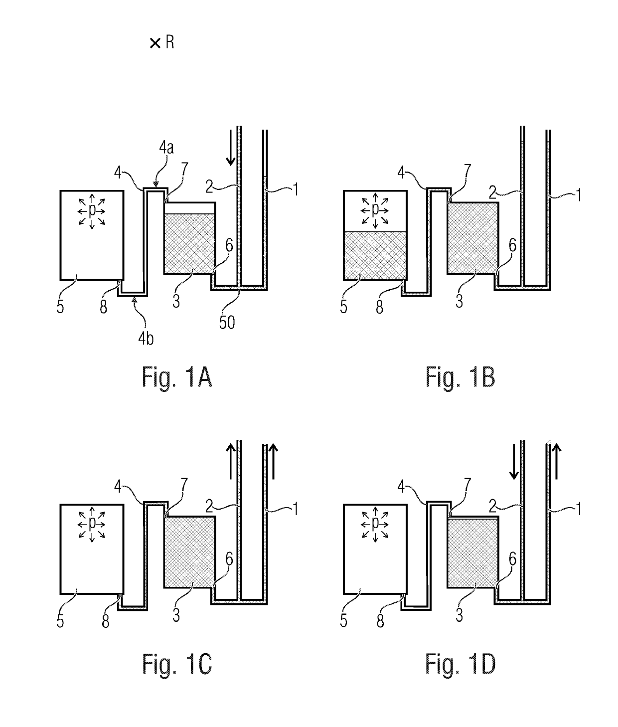
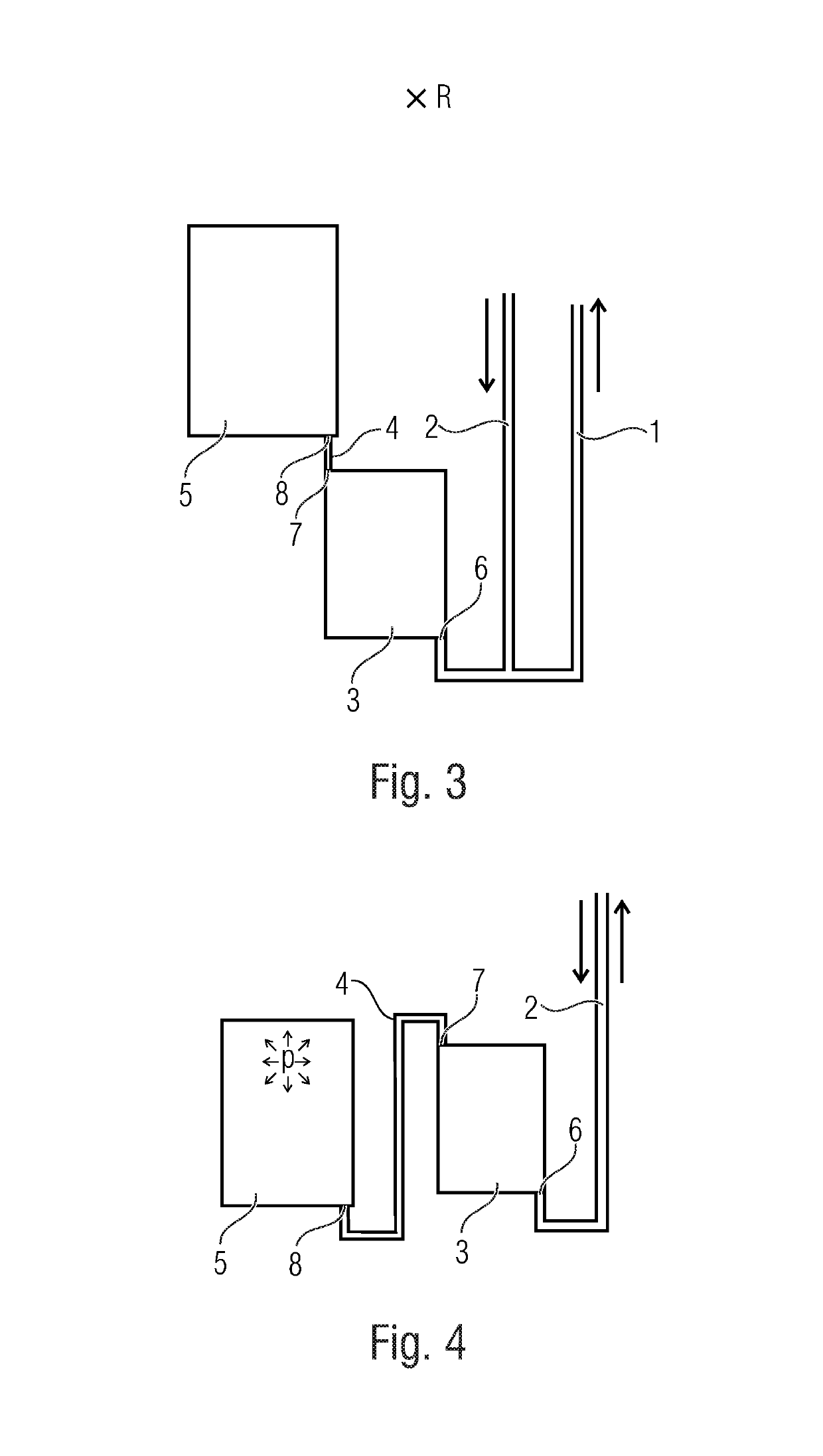
[0040]Before embodiments of the invention will be explained in more detail, it shall initially be noted that examples of the invention may be applied, in particular, in the field of centrifugal microfluidics, which is about processing liquids within the picoliter to milliliter ranges. Accordingly, the fluidic structures may have suitable dimensions within the micrometer range for handling corresponding volumes of liquid. In particular, embodiments of the invention may be applied in centrifugal-microfluidic systems as are known, for example, by the name of “Lab-on-a-Disk”.

[0041]Whenever the expression radial is used herein, what is meant in each case is radial in relation to the center of rotation about which the fluidic module, or the rotor, can be rotated. In the centrifugal field, a radial direction away from the center of rotation is radially descending, and a radial direction toward the center of rotation is radially ascending. A fluid channel whose beginning is located closer t...


PUM


Abstract

A fluidic module rotatable about a center of rotation includes a first compression chamber having a fluid inlet and a fluid outlet, a second compression chamber having a fluid inlet, a first fluid channel connected to the first chamber via the fluid inlet of the first chamber, and a second fluid channel connecting the fluid outlet of the first chamber to the fluid inlet of the second chamber. Due to rotation of the fluidic module a liquid may be centrifugally driven into the first chamber and the second fluid channel through the first fluid channel, and thereby a compressible medium may be entrapped and compressed within the second chamber. By lowering the rotary frequency and due to the resultant expansion of the compressible medium, liquid may be driven out of the second fluid channel into the first chamber, out of the first chamber into and through an outlet channel.

Description

CROSS-REFERENCE TO RELATED APPLICATIONS[0001]This application is a continuation of copending International Application No. PCT / EP2015 / 062956, filed Jun. 10, 2015, which is incorporated herein by reference in its entirety, and additionally claims priority from German Application No. 10 2014 211121.8, filed Jun. 11, 2014, which is also incorporated herein by reference in its entirety.[0002]The present invention relates to a fluidic module, a device and a method for handling liquid which are suitable, in particular, for handling—e.g. retaining and releasing and / or pumping—liquid within a centrifugal-microfluidic system.BACKGROUND OF THE INVENTION[0003]Centrifugal microfluidics deals with handling of liquids within the pl to ml ranges in rotating systems. Such systems are mostly disposable polymer cartridges used in or instead of centrifuge rotors, with the intention of enabling completely novel processes which cannot be performed by manual processes or pipetting robots because of the p...

Claims


Application Information

Patent Timeline
Patent Type & Authority Patents(United States)
IPC IPC(8): B01L3/00
CPCB01L3/50273B01L3/502746B01L2200/0621B01L2400/084B01L2300/0803B01L2300/087B01L2400/0409B01L2200/0684
Inventor SCHWEMMER, FRANKZEHNLE, STEFFENPAUST, NILSMARK, DANIEL
Owner HAHN SCHICKARD GESELLSCHAFT FUER ANGEWANDTE FORSCHUNG EV
Features
  • R&D
  • Intellectual Property
  • Life Sciences
  • Materials
  • Tech Scout
  • Unparalleled Data Quality
  • Higher Quality Content
  • 60% Fewer Hallucinations
Learn More