Check patentability & draft patents in minutes with Patsnap Eureka AI!

Coupler with quick release handle and valve assemblies

a technology of valve assembly and handle, which is applied in the direction of valve operating means/releasing devices, couplings, transportation and packaging, etc., can solve the problems of significant downtime and drawbacks, prone to wear of various components of the bottom loading coupler, and particularly the seal, and achieve the effect of quick disassembly and reassembling

Active Publication Date: 2019-08-27
KNAPPCO CORP
View PDF7 Cites 0 Cited by
  • Summary
  • Abstract
  • Description
  • Claims
  • Application Information

AI Technical Summary

Problems solved by technology

The various components of the bottom loading coupler, and particularly the seals, may be prone to wear.
As the components wear, the bottom loading coupler may not function properly, thus presenting a risk of uncontrolled release of product from the bottom loading coupler.
Such a process of disassembling and reassembling a bottom loading coupler can take up to several hours, which can lead to significant downtime and the drawbacks associated therewith.

Method used


Image

  • Coupler with quick release handle and valve assemblies
  • Coupler with quick release handle and valve assemblies
  • Coupler with quick release handle and valve assemblies

Examples


Embodiment Construction

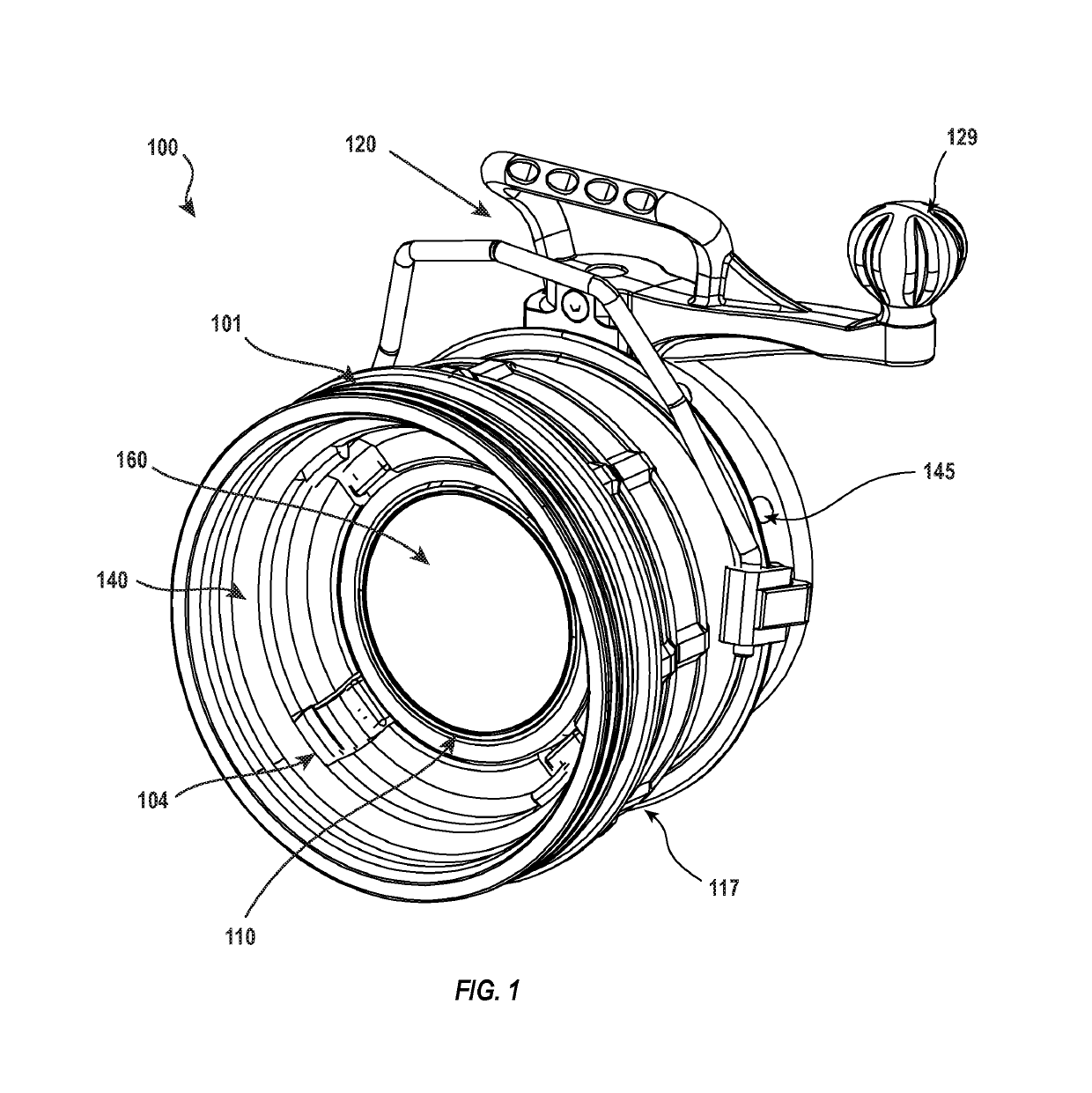
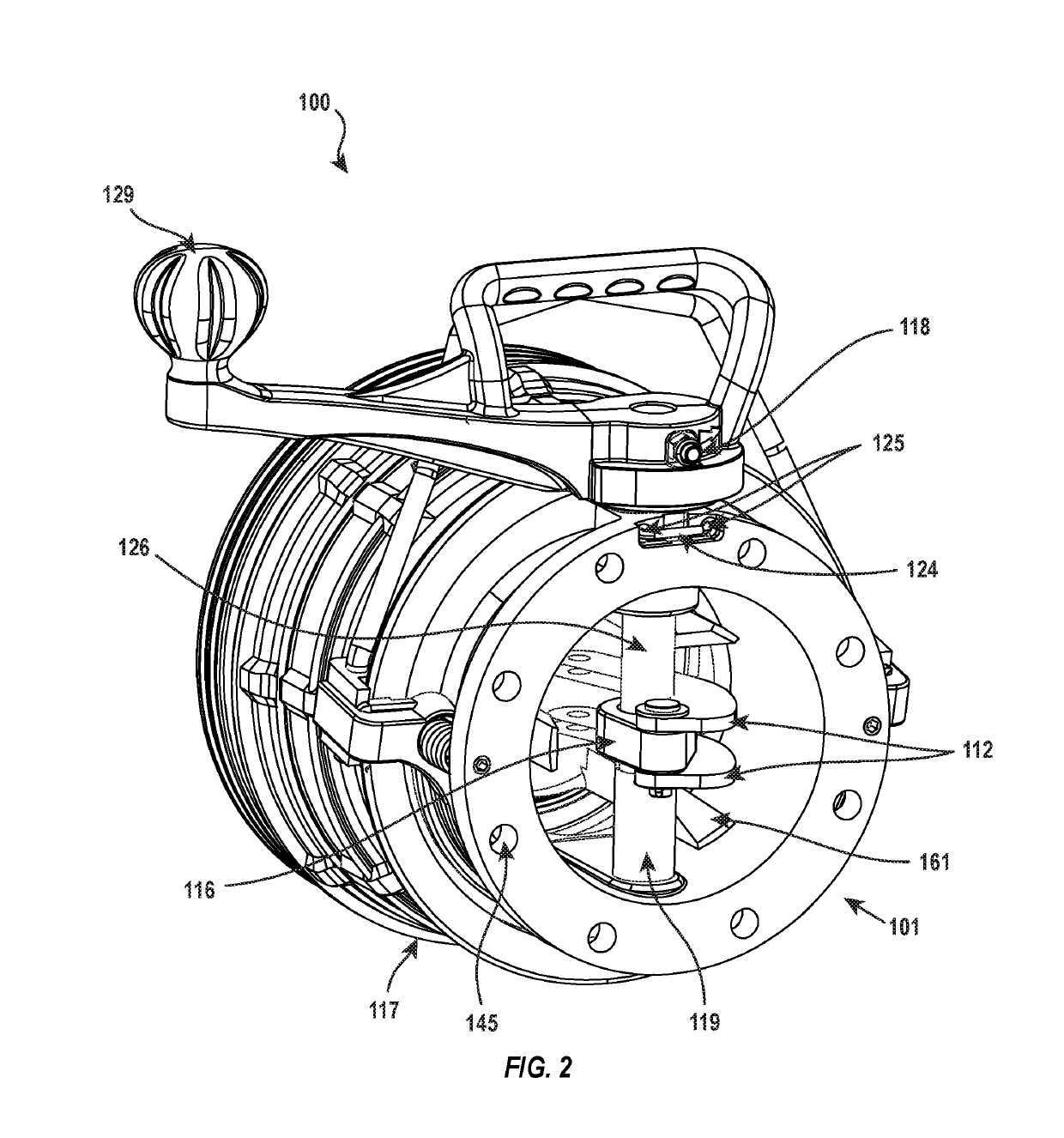
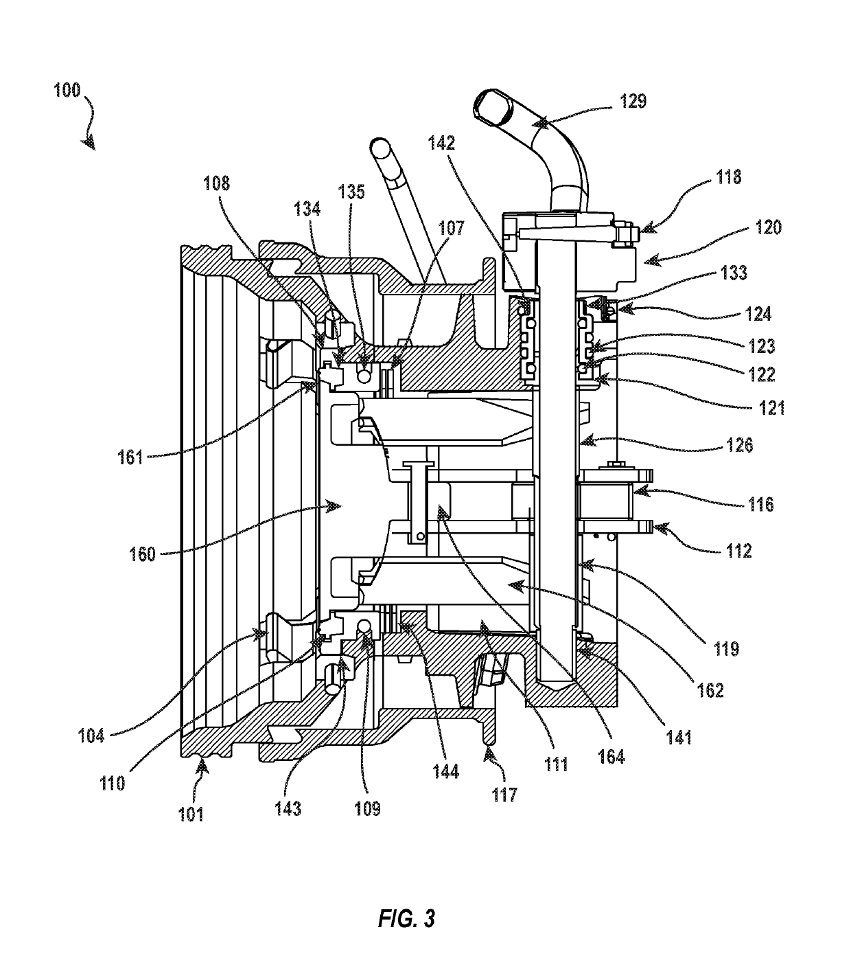
[0015]The present disclosure relates to coupling devices that can be quickly disassembled and reassembled to allow for repair or replacement of worn components in a timely manner. For example, in one embodiment, a fluid coupling includes a body, a poppet valve assembly, a handle shaft assembly, and a retention member. The body has a fluid conduit, a through-hole extending through a sidewall, and one or more openings that extend between an external surface of the body and an interior of the through hole. The poppet valve assembly is disposed within the fluid conduit and is selectively movable between an open position and a closed position. The handle shaft assembly extends through the through-hole and into the fluid conduit and is interconnected with the poppet valve assembly such that the handle shaft assembly can be actuated to move the poppet valve assembly between the open position and the closed position. The retention member is insertable through the one or more openings and in...


PUM


Abstract

A fluid coupling includes a body, a poppet valve assembly, a handle shaft assembly, and a retention member. The body has a fluid conduit, a through-hole extending through a sidewall, and one or more openings that extend between an external surface of the body and an interior of the through hole. The poppet valve assembly is disposed within the fluid conduit and is selectively movable between an open position and a closed position. The handle shaft assembly extends through the through-hole and into the fluid conduit and is interconnected with the poppet valve assembly such that the handle shaft assembly can be actuated to move the poppet valve assembly between the open position and the closed position. The retention member is insertable through the one or more openings and into the through-hole to interact with the handle shaft assembly to selectively hold the handle shaft assembly in the body.

Description

[0001]This application claims priority to and the benefit of U.S. Provisional Application No. 62 / 339,338, filed May 20, 2016, and entitled COUPLER WITH QUICK RELEASE HANDLE AND VALVE ASSEMBLIES, the entire content of which is incorporated herein by reference.BACKGROUND1. Technical Field[0002]Exemplary embodiments of the present disclosure relate to fluid system components. More particularly, exemplary embodiments of the present disclosure relate to couplers that can be quickly disassembled and reassembled for servicing.2. The Relevant Technology[0003]Transferring liquid product from large volume storage tanks into tank trucks or rail cars involves moving the liquid product through a fixed pipeline riser to storage containers of various sizes and orientations located in or on the tank trucks or rail cars. The various configurations of tank trucks and rail cars may require a flexible fluid transfer system such as a loading arm assembly. The loading arm assembly is a section of pipelin...

Claims


Application Information

Patent Timeline
Patent Type & Authority Patents(United States)
IPC IPC(8): B65D90/66F16L37/40F16K31/60F16K31/52F16L37/20
CPCF16K31/52F16L37/20F16L37/40F16K31/602F16K1/32F16K31/44B65D90/66
Inventor ROTH, JOSEPH P.MORROW, DAVIDWEJDMAN, KRZYSZTOFHUDSON, STEPHENTAING, SHIANG
Owner KNAPPCO CORP
Features
  • R&D
  • Intellectual Property
  • Life Sciences
  • Materials
  • Tech Scout
  • Unparalleled Data Quality
  • Higher Quality Content
  • 60% Fewer Hallucinations
Learn More