Check patentability & draft patents in minutes with Patsnap Eureka AI!

Wireless base station and frequency allocation method

a wireless communication system and wireless resource technology, applied in the field of wireless communication systems, frequency allocation methods, and methods for allocating wireless resources, can solve the problems of insufficient allocation efficiency or utilization efficiency of wireless resources for communicating data signals between terminals and base stations, and achieve the effect of improving allocation efficiency or utilization efficiency of wireless resources

Active Publication Date: 2019-10-15
PANASONIC INTELLECTUAL PROPERTY MANAGEMENT CO LTD
View PDF8 Cites 0 Cited by
  • Summary
  • Abstract
  • Description
  • Claims
  • Application Information

AI Technical Summary

Benefits of technology

This approach enhances the allocation efficiency and utilization of wireless resources by reducing communication interference and simplifying the resource allocation process, allowing for more effective communication of user data between terminals and base stations.

Problems solved by technology

In the technology described in NPL 1 to NPL 3, allocation efficiency or utilization efficiency of the wireless resource for communicating the data signal between the terminal and the base station is not sufficient.

Method used


Image

  • Wireless base station and frequency allocation method
  • Wireless base station and frequency allocation method
  • Wireless base station and frequency allocation method

Examples


first exemplary embodiment

(First Exemplary Embodiment)

[0030]FIG. 1 is a block diagram showing a configuration example of wireless communication system 10 of a first exemplary embodiment. Wireless communication system 10 includes one or more terminals 100 and one or more base stations 200. Terminal 100 and base station 200 are connected through a wireless link. Terminal 100 is an example of a wireless terminal, and base station 200 is an example of the wireless base station.

[0031]Wireless communication system 10 is a heterogeneous network in which base station 200 to which terminal 100 is to be connected has various wireless standards, and terminal 100 communicates with base station 200. In the heterogeneous network, different wireless communication methods (for example, radio access technologies (RATs)) or base stations 200 having different cell radii coexist. For example, in the heterogeneous network, a plurality of types of wireless standards coexist, and base stations 200 having different cell radii overl...

second exemplary embodiment

(Second Exemplary Embodiment)

[0102]In a second exemplary embodiment, the macrocell base station determines a radio frequency to be used in the communication of the user data between the terminal and the small cell base station. In the present exemplary embodiment, it may be assumed that the extraction of the connection base station to which terminal 100 is connected is completed.

[0103]Wireless communication system 10B according to the present exemplary embodiment includes terminal 100B, macrocell base station 200A2, and small cell base station 200B2. In wireless communication system 10B according to the present exemplary embodiment, an arrangement example of the devices (terminal 100B, macrocell base station 200A2, and small cell base station 200B2) is the same as that in FIG. 1, and the illustration and description thereof will be omitted.

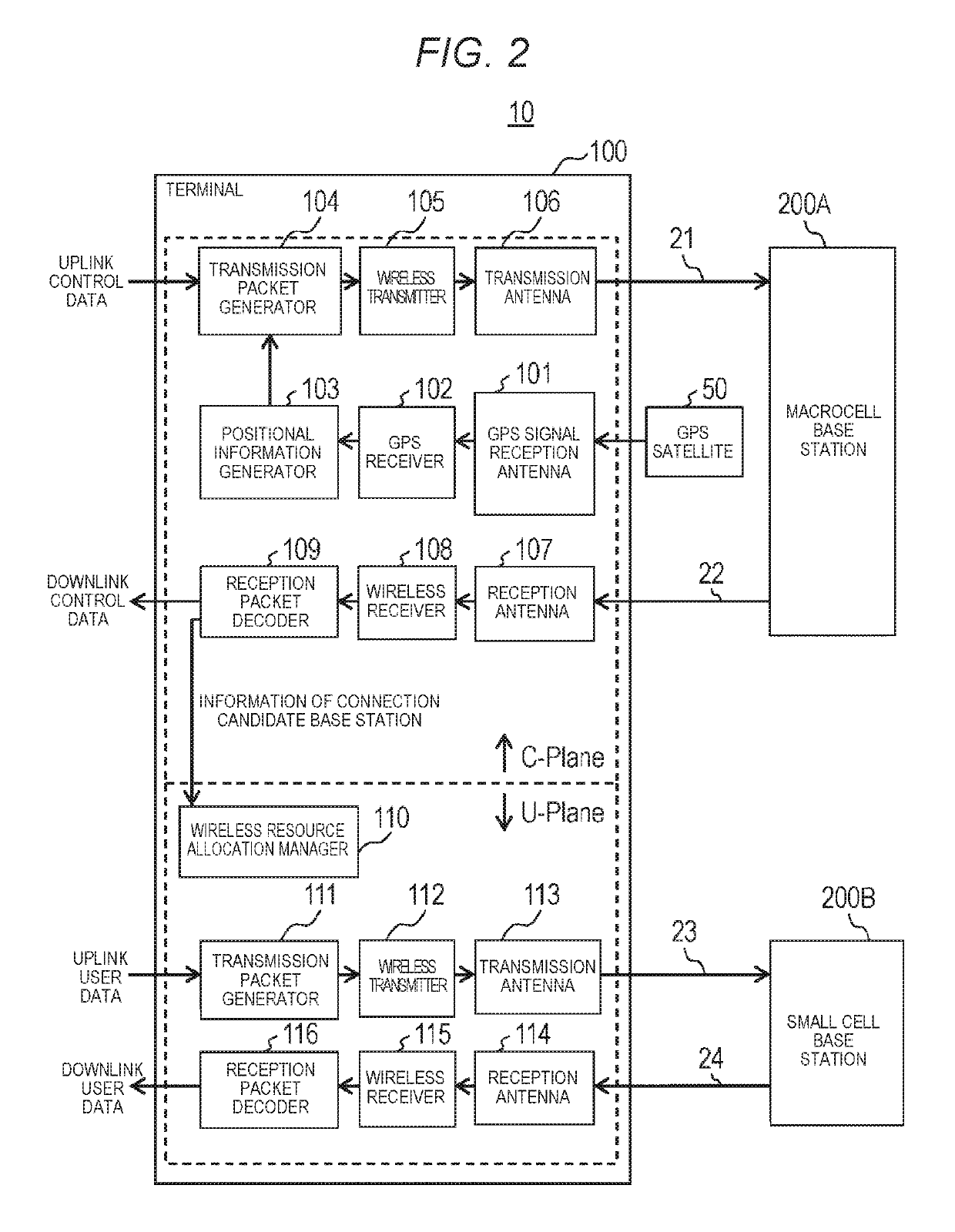
[0104]FIG. 7 is a block diagram showing a configuration example of terminal 100B. Terminal 100B includes a configuration section for the C-plane ...


PUM


Abstract

A wireless base station extracts a connection base station which communicates user data with a wireless communication terminal from a plurality of other wireless base stations, and extracts an allocation candidate of a wireless frequency regarding communication of the user data between the connection base station and the wireless communication terminal based on information of an utilization result of a wireless frequency regarding communication of the user data of each of the other wireless base stations.

Description

TECHNICAL FIELD[0001]The present disclosure relates to a wireless base station, a wireless communication system, a frequency allocation method, and a method for allocating a wireless resource.BACKGROUND ART[0002]In recent years, in a wireless communication system in which terminals and wireless base stations are connected to a network, a heterogeneous network has been examined (for example, see NPL 1 to NPL 3). NPL 1 to NPL 3 describe a technology (C / U splitting) in which the base stations are split into the base station that uses a control signal (C-plane) and the base station that uses a data signal (U-plane) in the heterogeneous network.CITATION LISTNon Patent Literature[0003]NPL 1: Seigo Nakao, Tetsuya Yamamoto, Shozo Okasaka, and Hidetoshi Suzuki, “Activities on heterogeneous networks for 5G—C-plane / U-plane Splitting Control in Heterogeneous Networks,” IEICE Technical Report, The Institute of Electronics, Information and Communication Engineers, October 2014, pp. 83-88[0004]NPL...

Claims


Application Information

Patent Timeline
Patent Type & Authority Patents(United States)
IPC IPC(8): H04W72/04H04W72/10H04W16/32H04W92/20H04W88/02H04W88/08
CPCH04W16/32H04W72/0453H04W72/27H04W72/52H04W92/20H04W72/20H04W72/56H04W88/02H04W88/08
Inventor KATO, OSAMU
Owner PANASONIC INTELLECTUAL PROPERTY MANAGEMENT CO LTD
Features
  • R&D
  • Intellectual Property
  • Life Sciences
  • Materials
  • Tech Scout
  • Unparalleled Data Quality
  • Higher Quality Content
  • 60% Fewer Hallucinations
Learn More