Check patentability & draft patents in minutes with Patsnap Eureka AI!

Sensor bracket

a technology of sensor and main body, applied in the field of sensor bracket, can solve the problems of difficulty in controlling the positioning between the on-board camera main body, inability to accurately detect obstacles, etc., and achieve the effect of improving the accuracy of processing the detection information detected by the sensor

Active Publication Date: 2019-11-12
HONDA MOTOR CO LTD
View PDF17 Cites 5 Cited by
  • Summary
  • Abstract
  • Description
  • Claims
  • Application Information

AI Technical Summary

Benefits of technology

[0008]Note that when a bracket is attached to a curved windshield, in view of the stability and for improving the appearance after being attached to the windshield, a curved bracket may be devised.
[0014]With such a configuration, the front surface of the bracket body becomes the contact surface between the bracket body and the glass, and the surface, serving as an attachment surface, that is opposite the planar portions is adhered to the glass with an adhesive or the like. In such a case, the distances between the attachment surface and the planar portions become smaller and the accuracy in detecting the inclination of the bracket body with respect to the glass can be improved.
[0016]According to the angle calculating method of the present embodiment, the positional relationship between the sensor and the bracket body is determined uniquely when the bracket body is mounted on the sensor. Accordingly, the angle in which the sensor is fitted to the glass can be calculated from the inclination angle of the bracket body with respect to the glass. Furthermore, by using the fitting angle, the accuracy in processing the detection information detected by the sensor can be improved.

Problems solved by technology

Although there is no description of the above in Japanese Unexamined Patent Application Publication No. 2013-203250, when attaching a curved bracket to a curved windshield, if the bracket becomes inclined, it is difficult to control the positioning between the on-board camera main body and the curved bracket and, disadvantageously, the obstacle and the like may not be accurately detected due to the axis deviation of the camera not being corrected.

Method used


Image

  • Sensor bracket
  • Sensor bracket
  • Sensor bracket

Examples


Embodiment Construction

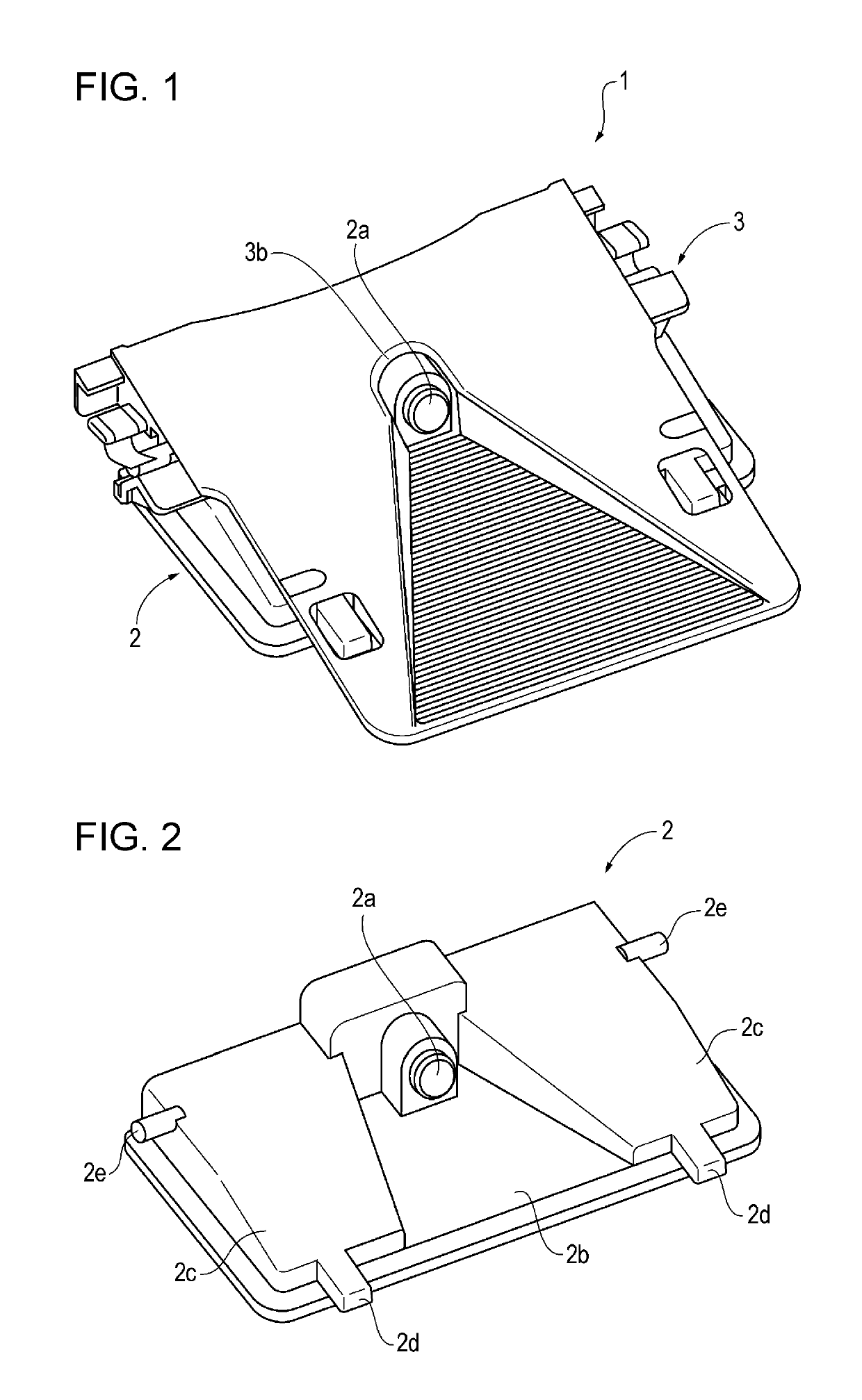
[0023]FIG. 1 illustrates a configuration in which a camera corresponding to a sensor of the present disclosure that detects the surroundings of a vehicle is mounted on a sensor bracket of the present disclosure. Hereinafter, the above configuration is referred to as a camera unit 1.

[0024]FIG. 1 is a perspective view of the camera unit 1 viewed obliquely from above. The camera unit 1 includes a camera 2 that is a sensor that performs imaging of an image in front of the vehicle, and a bracket 3 that is fixed to the windshield of the vehicle by being adhered thereon. Note that, hereinafter, description is given while the front of the vehicle is a front direction (a front side).

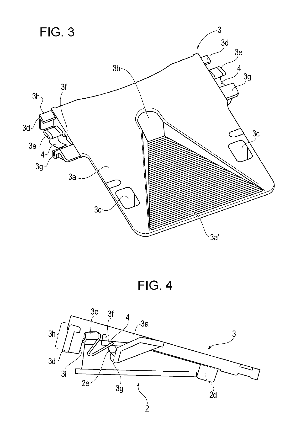
[0025]As illustrated in the drawings, the camera 2 is mounted on the bracket 3 from a lower side of the bracket 3 with an engaging mechanism described later. An opening 3b into which a lens 2a of the camera 2 is inserted is provided on an upper surface of the bracket 3. With the above, the camera 2 is capable of ...


PUM


Abstract

A sensor bracket includes a plate-shaped bracket, a front surface of which is attached to an inner surface of a windshield of a vehicle, the plate-shape bracket having a camera that detects a state around a vehicle mounted on a back surface, reference surfaces provided on a back surface of the plate-shaped bracket, the reference surfaces being parallel to each other.

Description

CROSS REFERENCES TO RELATED APPLICATIONS[0001]The present application claims priority under 35 U.S.C. § 119 to Japanese Patent Application No. 2016-060378, filed Mar. 24, 2016, entitled “Sensor Bracket.” The contents of this application are incorporated herein by reference in their entirety.BACKGROUND[0002]1. Field[0003]The present disclosure relates to a sensor bracket used to attach an on-board camera or the like.[0004]2. Description of the Related Art[0005]Hitherto, a technique is known that accurately detects an obstacle and a pedestrian, a position of a traffic lane, whether a headlight of an oncoming vehicle is on, and the like by performing imaging of a portion in front of a vehicle with an on-board camera. In such a case, the on-board camera is mounted on a bracket that is adhered to a windshield.[0006]For example, in Japanese Unexamined Patent Application Publication No. 2013-203250, while bosses of an on-board camera main body are hooked to hook-shaped portions, the on-boa...

Claims


Application Information

Patent Timeline
Patent Type & Authority Patents(United States)
IPC IPC(8): H04N5/225B60R11/04B60R11/00
CPCB60R11/04H04N5/2252B60R2011/0026B60R2011/0084B60R2011/0071B60R2011/0075H04N23/51
Inventor KASAI, KEITATOKIWA, MITSURUMATORI, TADAHIROOHMOTO, TAKAHIRO
Owner HONDA MOTOR CO LTD
Features
  • R&D
  • Intellectual Property
  • Life Sciences
  • Materials
  • Tech Scout
  • Unparalleled Data Quality
  • Higher Quality Content
  • 60% Fewer Hallucinations
Learn More