Supercharge Your Innovation With Domain-Expert AI Agents!

Systems and methods for determining the temperature and/or level of a molten metal bath in a vessel

a technology temperature, which is applied in the field of systems and methods for measuring the temperature and/or the level of molten metal bath in such a vessel, can solve the problems of inability to determine, in real time, and lack of real time, and achieves accurate temperature data, target temperature and chemistries are often missed, and the temperature of molten metal is not known

Active Publication Date: 2020-02-25
BERRY METAL
View PDF1 Cites 0 Cited by
  • Summary
  • Abstract
  • Description
  • Claims
  • Application Information

AI Technical Summary

Problems solved by technology

However, a common impedance to being able to achieve that goal is the inability to determine, in real time, the temperature of the molten steel bath inside a BOF.
As a result of lacking real time, accurate temperature data, target temperatures and chemistries are often missed.
Failure to achieve the target temperatures and chemistries during the metal melting process can result in inefficiencies and may even result in having to reinitiate the heating process, resulting in significant economic impact.
This lack of ability to determine temperature in real time results in a lack of efficiency that not only applies to BOF's in the steel industry, but also to electric arc furnaces (EAF's) and induction furnaces.
As a result, using temperature sensors inside the BOF to take temperature readings is not typically feasible.
Furthermore, to the extent that using temperature sensors inside the BOF has been attempted, the high temperatures at which the BOF operates tend to substantially impact the life of the sensors.
Because the temperature of the molten metal bath in a BOF varies greatly with stratification of the level (height) of the bath and proximity to the heating element, none of these approaches effectively provide accurate temperature data with regard to the overall bath inside the BOF.

Method used


Image

  • Systems and methods for determining the temperature and/or level of a molten metal bath in a vessel
  • Systems and methods for determining the temperature and/or level of a molten metal bath in a vessel
  • Systems and methods for determining the temperature and/or level of a molten metal bath in a vessel

Examples


first embodiment

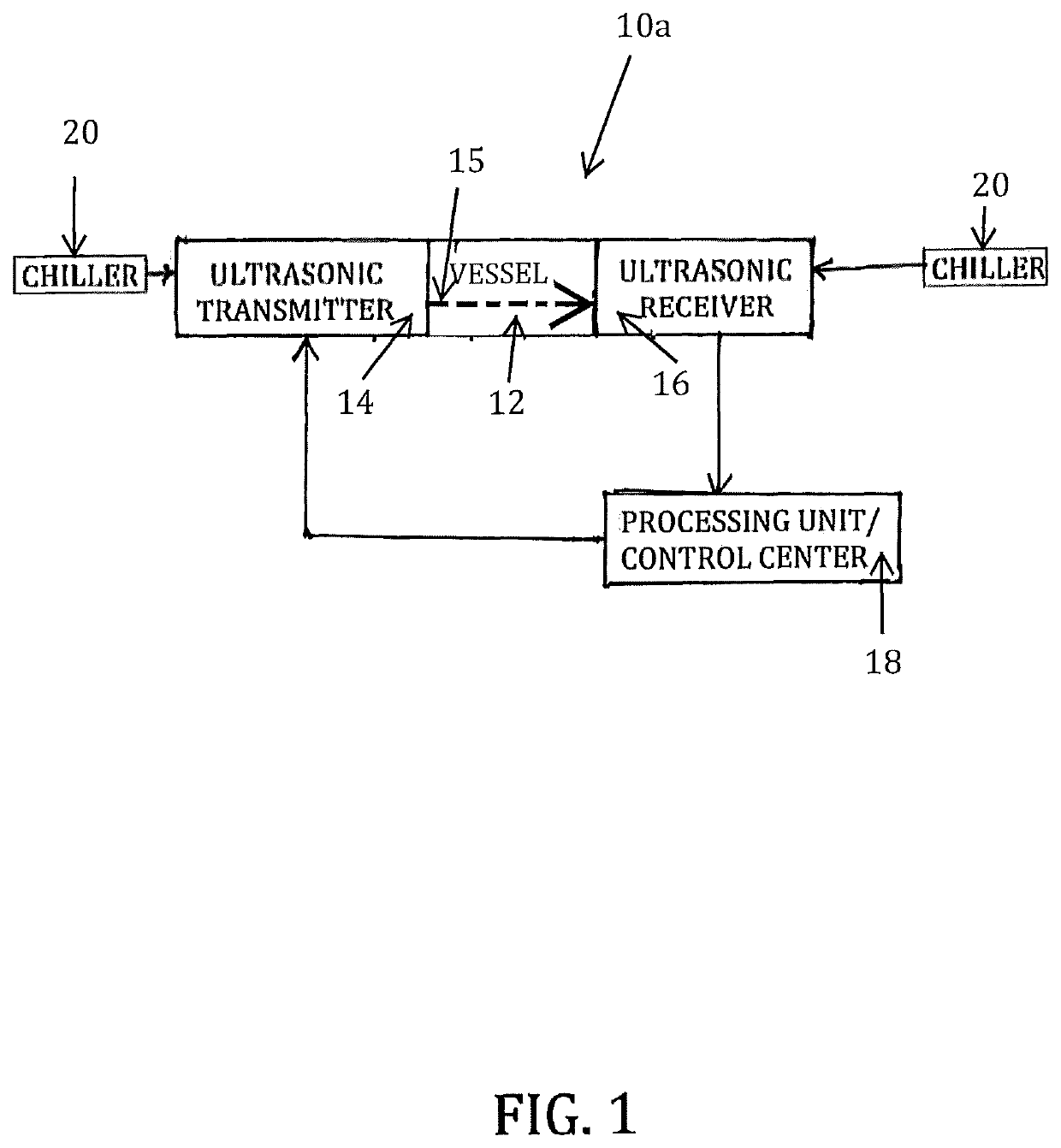
FIG. 1 is a block diagram of a system 10a provided in accordance with the present invention. As shown, the system 10a comprises a vessel 12, such as a BOF, for use in a metal making process. The vessel 12 may comprise multiple layers of refractory material, such as fire brick, alumina, silica, etc., as well as one or more internal insulating layers, such as gunite or other shotcrete material. Regardless of the exact structure of the vessel 12, during the metal making process, the vessel 12 contains a molten metal bath that is thermally processed as is customary in the industry.

As shown in FIG. 1, the system 10a provides that both an ultrasonic transmitter 14 and an ultrasonic receiver 16 are disposed about the vessel 12. Both the ultrasonic transmitter 14 and the ultrasonic receiver 16 can either be disposed directly on the vessel 12, or they can be spaced away therefrom in order to effectively insulate them with regard to the high operating temperatures of the vessel 12. The ultras...

second embodiment

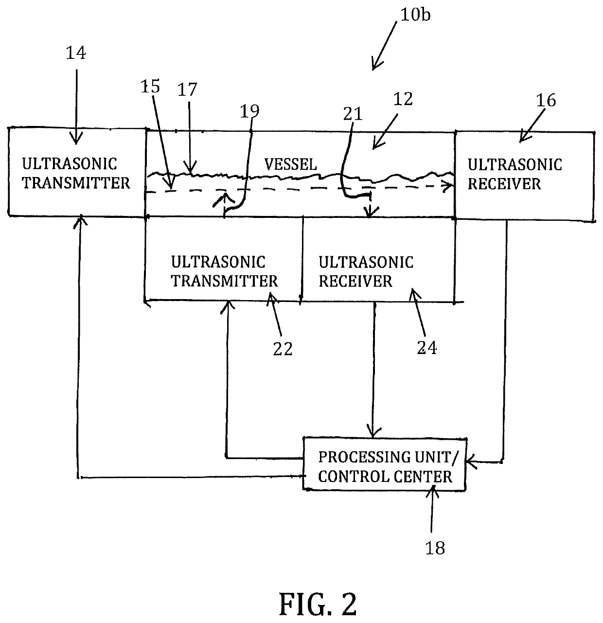
FIG. 2 is a block diagram of a system 10b which is in accordance with the present invention. The system 10b is like the system 10a shown in FIG. 1, and includes an ultrasonic transmitter 14, ultrasonic receiver 16, and a processing unit (i.e., control center) 18, wherein an ultrasonic signal (represented using a dashed line which is identified using reference numeral 15). However, in addition, the system 10b shown in FIG. 2 employs an additional ultrasonic transmitter 22 and receiver 24. The additional ultrasonic transmitter 22 and receiver 24 are disposed under the vessel 12 or on the bottom of the vessel 12, and are used by the processing unit 18 to determine the level (i.e., height) of the molten metal bath in the vessel 12 (in FIG. 2, the height of the molten metal bath is indicated using reference numeral 17). Specifically, preferably the ultrasonic transmitter 22 and ultrasonic receiver 24 are in close proximity to each other, and the ultrasonic transmitter 22 sends an ultraso...

third embodiment

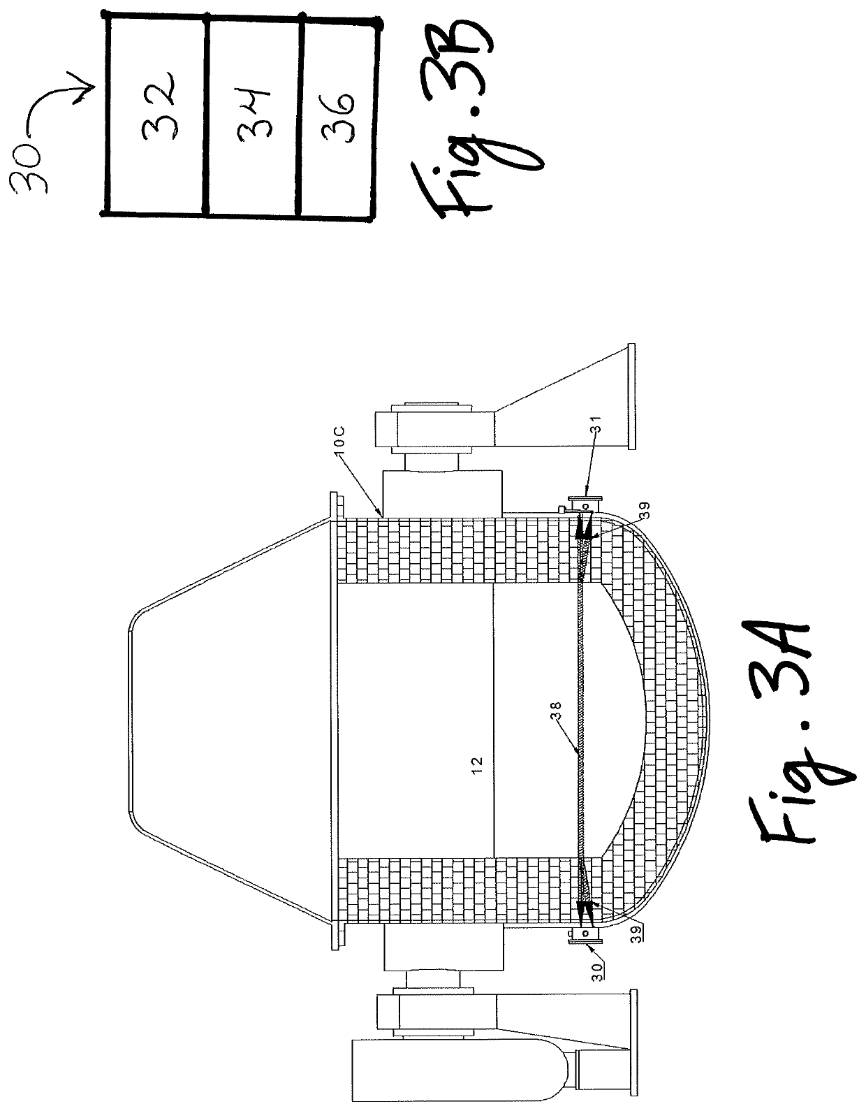
FIG. 3A shows an illustration of a system 10c which is in accordance with the present invention. The system 10c is like the system 10a, and 10b shown in FIGS. 1 and 2, respectively, except that system 10c comprises first and second sensor modules 30, 31. As shown in FIG. 3B each sensor module 30, 31 (only module 30 is shown) comprises at least one ultrasonic transmitter 32, at least one ultrasonic receiver 34, and a chiller 36. The modules 30, 31 are preferably protected from the heat of the bath by a chiller 36, which may or may not be cooled with water, air, or some other appropriate coolant.

FIG. 3A shows a “pulse-echo” method of signal transmission in the system 10c, which enables self-calibration of the methods for determining the temperature and / or level of a molten metal bath in a vessel 12, as described herein. This method calculates the thickness of the walls of the vessel 12 and is used to determine the change in wall thickness for the purpose of self-calibration. The walls...


PUM

PropertyMeasurementUnit
temperatureaaaaaaaaaa
ultrasonicaaaaaaaaaa
meltingaaaaaaaaaa

Abstract

The present invention preferably comprises a system and method for measuring and / or continuously monitoring the temperature and / or height of a molten metal bath in a vessel. Specifically, an ultrasonic transmitter and an ultrasonic receiver are disposed about sides of the vessel and are used to send and receive an ultrasonic signal in order to detect the temperature of the bath. More specifically, the ultrasonic transmitter is configured to send an ultrasonic signal through the vessel, and the ultrasonic receiver is configured to receive that ultrasonic signal after it has travelled through the vessel (comprising the molten metal bath). The ultrasonic receiver provides at least one signal to a processing unit (i.e., control center), which processes the at least one signal to determine the temperature and / or level of the molten metal bath. The invention may further comprise chillers to protect the transmitter and receiver from the heat of the bath.

Description

FIELD OF THE INVENTIONThe present invention generally relates to vessels for melting metal. More specifically, it relates to systems and methods for measuring the temperature and / or the level of a molten metal bath in such a vessel, preferably using ultrasonic thermometry.BACKGROUND OF THE INVENTIONIn the steel industry, the Basic Oxygen Furnace (BOF) is the primary steelmaking vessel in a steel mill. A general goal in the industry is to improve quality control while also reducing production time and cost. However, a common impedance to being able to achieve that goal is the inability to determine, in real time, the temperature of the molten steel bath inside a BOF. As a result of lacking real time, accurate temperature data, target temperatures and chemistries are often missed. Failure to achieve the target temperatures and chemistries during the metal melting process can result in inefficiencies and may even result in having to reinitiate the heating process, resulting in signific...

Claims


Application Information

Patent Timeline
Patent Type & Authority Patents(United States)
IPC IPC(8): G01K1/00G01K11/00G01N25/00G01K11/24G01F23/296C21C5/46F27D21/00F27B3/28F27D19/00C21C5/52
CPCG01F23/296G01K11/24C21C5/4673F27D21/0028F27B3/28F27D21/0014F27D2019/0003C21C2005/5288Y02P10/20
Inventor GREEN, EDWARD J.YUHAS, DONALD E.
Owner BERRY METAL
Features
  • R&D
  • Intellectual Property
  • Life Sciences
  • Materials
  • Tech Scout
  • Unparalleled Data Quality
  • Higher Quality Content
  • 60% Fewer Hallucinations
Learn More