Electronics device
a technology of electronic devices and devices, applied in pulse generators, pulse techniques, instruments, etc., can solve problems such as inability to receive reset signals, computer malfunctions, and out of control, and achieve the effect of reducing the size of the device and restoring the operation sta
- Summary
- Abstract
- Description
- Claims
- Application Information
AI Technical Summary
Benefits of technology
Problems solved by technology
Method used
Image


Examples
first embodiment
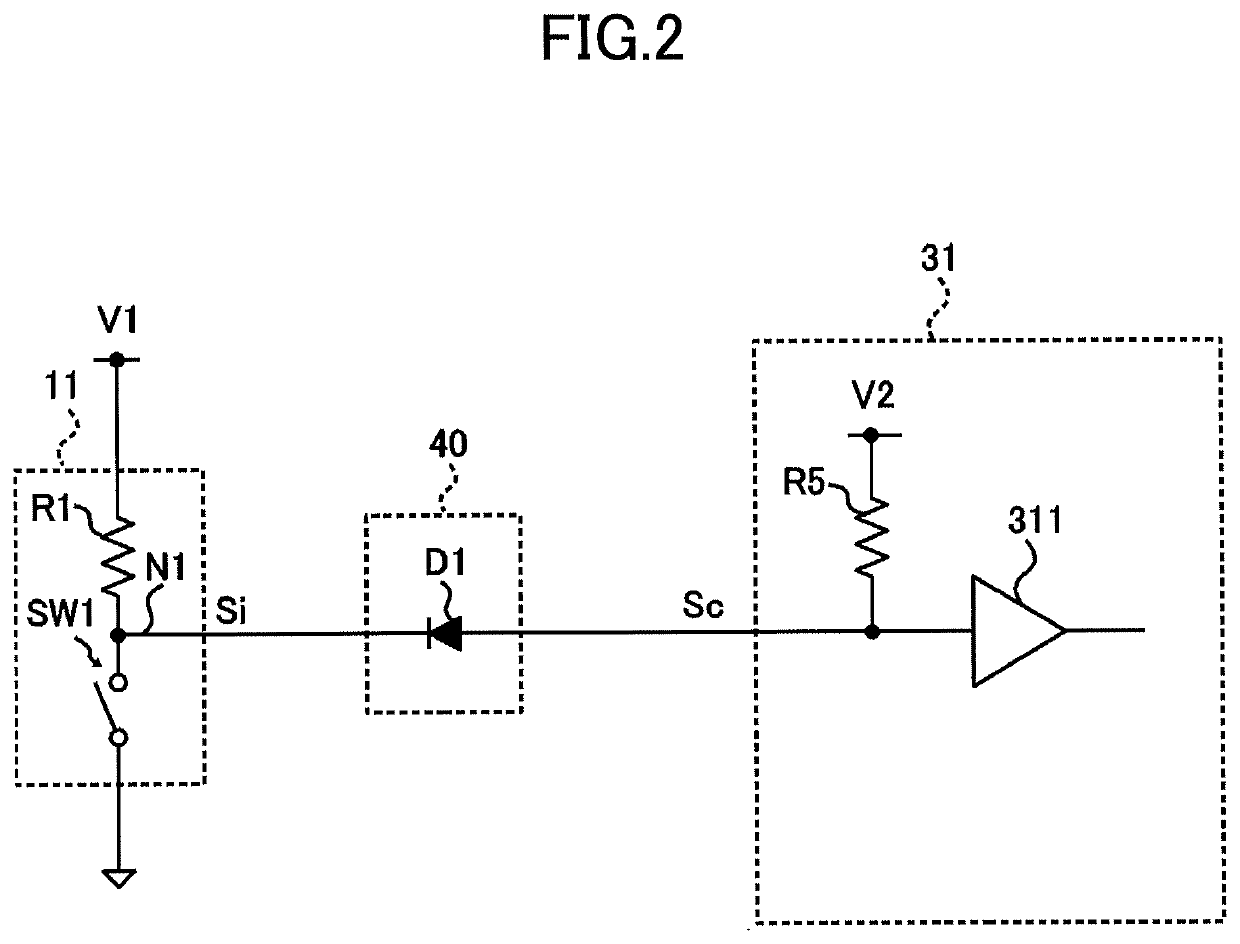
[0028]FIG. 1 is a diagram illustrating an example of a configuration of an electronic device according to a first embodiment. The electronic device illustrated in FIG. 1 includes a first circuit unit 10, a regulator 20, a second circuit unit 30, and a signal transmitting unit 40.
[0029]For example, the electronic device according to the present embodiment is a relatively small electronic device such as a wearable device or a portable terminal apparatus and includes a function to reset an operation state in accordance with an input operation of a user. As the device size becomes smaller, the area of a ground pattern of an electronic circuit becomes smaller and the ground potential easily fluctuates. Therefore, a reset function is required for when abnormality of an operation state occurs.
[0030]The regulator 20 outputs a second power supply voltage V2 based on a first power supply voltage V1 supplied from a battery (not illustrated) built in the electronic device or an external power s...
second embodiment
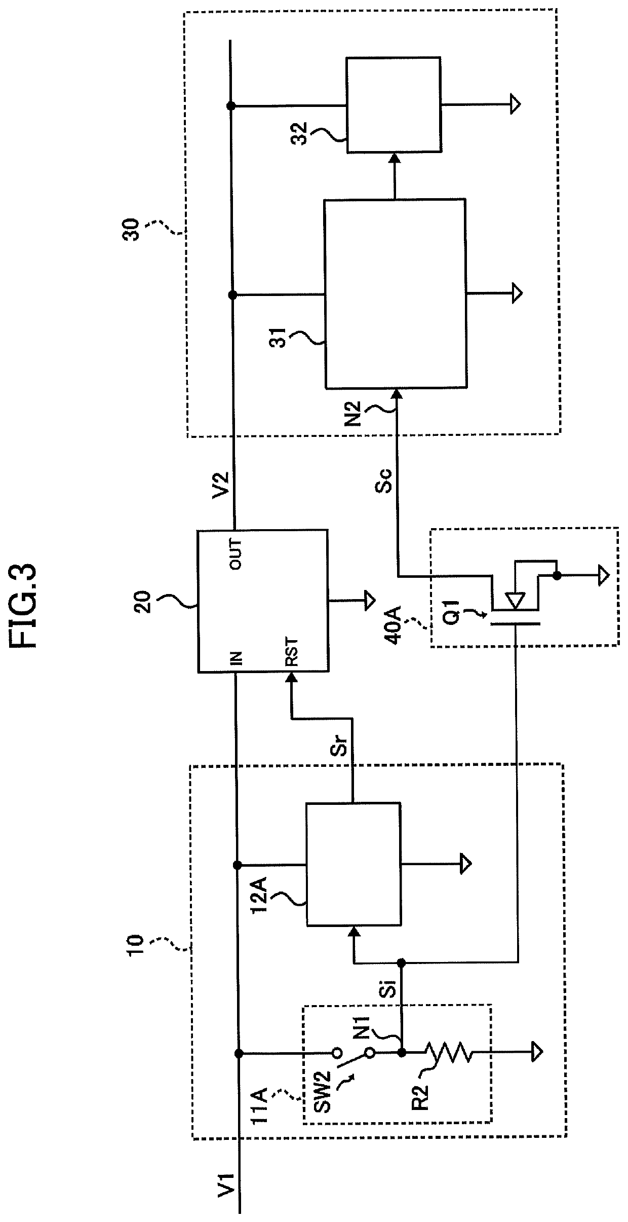
[0051]Next, a second embodiment of the present invention will be described with reference to FIG. 3 and FIG. 4. FIG. 3 is a diagram illustrating an example of a configuration of an electronic device according to the second embodiment. FIG. 4 is a diagram illustrating an example of a circuit that inputs a control signal Sc to the processing unit 31 in the electronic device, which is illustrated in FIG. 3. The electronic device, which is illustrated in FIG. 3 and FIG. 4, is obtained by respectively replacing the operation signal generating unit 11 and the reset unit 12 of the first circuit unit 10 of the electronic device, which is illustrated in FIG. 1, with an operation signal generating unit 11A and a reset unit 12A and replacing the signal transmitting unit 40 with a signal transmitting unit 40A. Other components of the electronic device that is illustrated in FIG. 3 are the same as those of the electronic device that is illustrated in FIG. 1.
[0052]As illustrated in FIG. 3, the op...
third embodiment
[0067]Next, a third embodiment of the present invention will be described. FIG. 5 is a diagram illustrating an example of a configuration of an electronic device according to the third embodiment. The electronic device, which is illustrated in FIG. 5, has a configuration similar to that of the electronic device, which is illustrated in FIG. 1, and includes a regulator 20A and a second circuit unit 30A.
[0068]The regulator 20A is a circuit that outputs a second power supply voltage V2A based on the first power supply voltage V1, and controls the second power supply voltage V2A so as to be substantially equal to the second power supply voltage V2 of the regulator 20, for example. Similar to the regulator 20, the regulator 20A stops the output operation of the second power supply voltage V2A in accordance with the reset signal Sr of the reset unit 12. Although the circuit system of the regulator 20A may be a dropper type or a switching type, in a case where a low noise circuit is requir...
PUM
 Abstract
Description
Claims
Application Information
 - R&D
- Intellectual Property
- Life Sciences
- Materials
- Tech Scout
- Unparalleled Data Quality
- Higher Quality Content
- 60% Fewer Hallucinations
Browse by: Latest US Patents, China's latest patents, Technical Efficacy Thesaurus, Application Domain, Technology Topic, Popular Technical Reports.
© 2025 PatSnap. All rights reserved.Legal|Privacy policy|Modern Slavery Act Transparency Statement|Sitemap|About US| Contact US: help@patsnap.com