Check patentability & draft patents in minutes with Patsnap Eureka AI!

Subsea pipeline connector method

a technology of subsea pipelines and connectors, which is applied in the direction of fluid loss/gain rate measurement, fluid tightness measurement, instruments, etc., can solve the problems of pipeline buoyancy, pipeline weight, and time it takes to apply any required coating,

Active Publication Date: 2020-04-14
BAUGH BENTON FREDERICK
View PDF21 Cites 2 Cited by
  • Summary
  • Abstract
  • Description
  • Claims
  • Application Information

AI Technical Summary

Benefits of technology

This solution significantly reduces connection time and costs by eliminating sequential operations, enabling faster and more efficient pipeline laying with reduced vessel time and mobilization costs, while ensuring a secure and leak-proof connection.

Problems solved by technology

The cost it takes to make the connection is a factor of the cost of the connection, the time it takes to make the connection, and the time it takes to do any required coating after the connection is made.
A major portion of the costs was simply the vessel time charge to make the connections.
A problem with this method is that in some cases the pipelines tend to be buoyant and need to be weighed down.
Shorter and infield pipelines typically do not justify the high mobilization costs and daily rate of a reel type barge method.
As a comparison, the mobilization cost of a modern reel pipelay vessel to a remote location can exceed the capital cost of a simpler jointed laying system placed on a local barge.

Method used


Image

  • Subsea pipeline connector method
  • Subsea pipeline connector method
  • Subsea pipeline connector method

Examples


Embodiment Construction

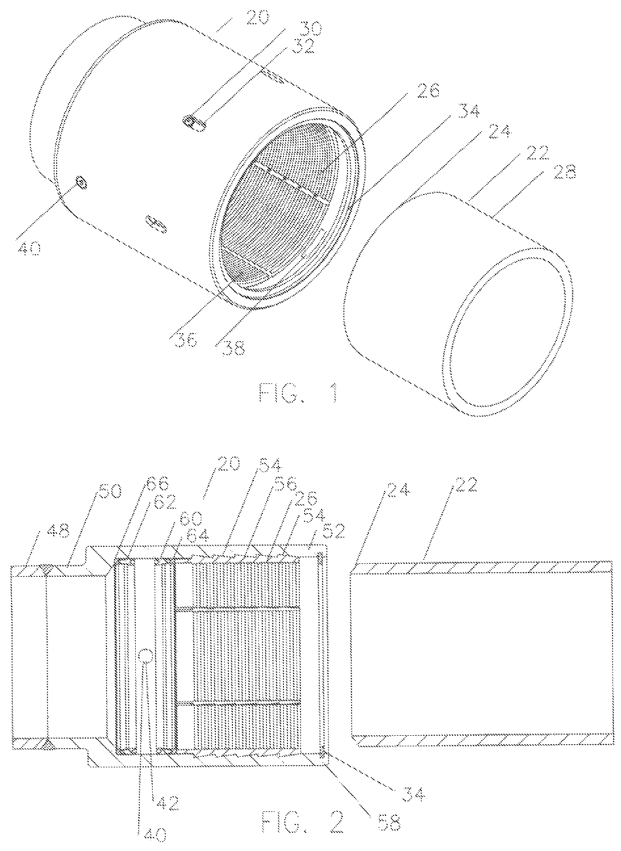
[0031]Referring now to FIG. 1, a perspective of a connector 20 and a plain end of pipe 22 are shown ready to be engaged. The plain end of pipe 22 will have a buttweld preparation 24 in anticipation of the normal connection process of welding. The connector 20 shows slip segments 26 are configured to engage the outer diameter 28 of plain end pipe 22. Slip segments 26 are retained in place by bolts 30 which slide along slots 32, as will be discussed later. Environmental seal 34 is shown ready to engage the outer diameter 28 of plain end pipe 22. As connector 20 allows plain end of pipe 22 to be fully coated prior to connection, and sharp teeth 36 of slip segments 26 will cut into the coatings to firmly engage the steel pipe, it means gaps will be introduced into the coating. The environmental seal 34 prevents continued galvanic corrosion of the pipeline at the gaps in the coating. Additionally, anodic material 38 can be placed in the area to further protect the pipeline from galvanic ...


PUM


Abstract

The method of providing a connector suited for quickly connecting and testing joints of pipe for a subsea pipeline and similar applications by concurrently locking, preloading, sealing and testing of the connection to eliminate the usual sequential time requirements for each of these operations. Additionally, time for coating and X-Ray inspection of the welded connection in critical path time are eliminated as the welding and coating operations are able to be done on shore in non-critical path time.

Description

TECHNICAL FIELD[0001]This invention relates to a method of providing a connector suited for quickly connecting and testing joints of pipe for a subsea pipeline and similar applications while eliminating the need for welding, X-ray, and coating operations.BACKGROUND OF THE INVENTION[0002]Offshore pipelines laid along the seafloor for the delivery of oil and gas from a source to an ultimate destination are manufactured of short joints of pipe as a manufacturing reality. These joints of pipe must be connected together in order to make a pipeline. The cost it takes to make the connection is a factor of the cost of the connection, the time it takes to make the connection, and the time it takes to do any required coating after the connection is made. A major portion of the costs was simply the vessel time charge to make the connections.[0003]Historically the connections have been made by welding the joints of the pipe together on a barge. The efficiency of this process was improved by pro...

Claims


Application Information

Patent Timeline
Patent Type & Authority Patents(United States)
IPC IPC(8): F16L1/26F16L13/10G01M3/28F16L17/10F16L13/11F16L21/08F16L1/18F16L25/06
CPCF16L13/103F16L1/18F16L21/08G01M3/2815F16L1/26F16L13/116F16L17/10F16L25/065G01M3/2853
Inventor BAUGH, BENTON FREDERICK
Owner BAUGH BENTON FREDERICK
Features
  • R&D
  • Intellectual Property
  • Life Sciences
  • Materials
  • Tech Scout
  • Unparalleled Data Quality
  • Higher Quality Content
  • 60% Fewer Hallucinations
Learn More