Check patentability & draft patents in minutes with Patsnap Eureka AI!

Thermoelectric generator

a generator and thermoelectric technology, applied in the direction of generator/motor, indirect heat exchanger, light and heating apparatus, etc., can solve the problems of inability to conduct electric power generation, micropower electronics cannot be freely installed at a place where they are required, and the installation site of the thermoelectric generator is restricted, so as to achieve more effective electric power generation

Active Publication Date: 2020-05-05
NAKANUMA TADASHI
View PDF21 Cites 1 Cited by
  • Summary
  • Abstract
  • Description
  • Claims
  • Application Information

AI Technical Summary

Benefits of technology

This design enables stable electricity generation from environmental temperature changes, enhancing installation flexibility and reducing dependence on external power sources or batteries, while improving power generation efficiency through controlled heat transfer and storage.

Problems solved by technology

Namely, in the conventional thermoelectric generators, an installation site of the thermoelectric generator is restricted because temperature difference between the source of heating and the source of cooling which are located adjacent to each other is used for electric power generation.
However, there arises a problem that the micropower electronics cannot be freely installed at a place where they are required because of the above-mentioned restriction of installation site of the thermoelectric generators.
However, according to the solar cell, the electric power generation cannot be conducted after dark, and the production of electricity is not stabilized because sunshine is significantly affected by weather and clouds, so that an electric storage device is required.

Method used


Image

  • Thermoelectric generator
  • Thermoelectric generator
  • Thermoelectric generator

Examples


Embodiment Construction

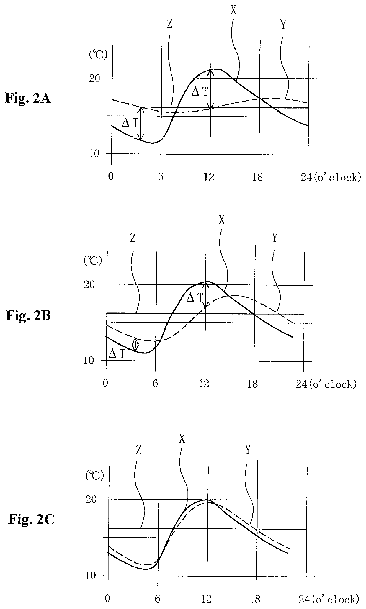
[0050]A preferred embodiment of the present invention will be described below with reference to accompanying drawings. A thermoelectric generator according to the present invention is designed to arrange in an environment whose temperature increases and decreases repeatedly. Here, the term “environment” includes, for example, the inside of outdoor air whose temperature is periodically changed during day and night, the neighborhood or surface of mechanical appliances which are arranged indoor and change temperature thereof according to operating condition and so on.

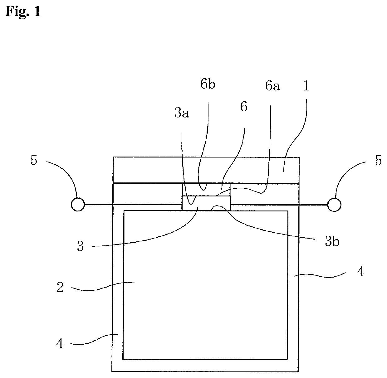
[0051]FIG. 1 is a longitudinal sectional view of a thermoelectric generator according to an embodiment of the present invention. In the embodiment shown in FIG. 1, the thermoelectric generator comprises a single thermal conductor 1 contacting with the environment to conduct thermal exchange with the environment, a single thermal accumulator 2, and at least one pair (in this embodiment, one pair) of a thermoelectric convers...


PUM


Abstract

A thermoelectric generator has a heat conducting body that exchanges heat with the environment according to environmental temperature changes, a heat storing body, and a thermoelectric conversion unit and thermal resistance body arranged between the heat conducting body and the heat storing body. One end of the thermal resistance body and one end of the thermoelectric conversion unit are in contact with each other. The other end of the thermal resistance body is in contact with the heat conducting body, and the other end of the thermoelectric conversion unit is in contact with the heat storing body. The surface of the heat storing body is covered by a covering layer having certain heat insulation properties. The temperature difference generated between the heat conducting body and the heat storing body is utilized to extract electric energy from the thermoelectric conversion unit.

Description

TECHNICAL FIELD[0001]The present invention relates to a thermoelectric generator which generates electricity by utilizing change of temperature of external environment so as to convert thermal energy into electric energy.BACKGROUND ART[0002]Energy harvesting has received attention in recent years. The energy harvesting is a technology of converting environmental energy such as heat, vibration, light and electromagnetic wave into electric power. As a technology concerning the energy harvesting, there exist in the prior art some thermoelectric generators of generating electric power from thermal energy by means of thermoelectric conversion module (See, Patent Documents 1-3).[0003]According to the conventional thermoelectric generators, on electric power generation, it is necessary to cause a certain amount of temperature difference between both sides of the thermoelectric conversion module by supplying heat to one side thereof by means of a source of heating and releasing heat from th...

Claims


Application Information

Patent Timeline
Patent Type & Authority Patents(United States)
IPC IPC(8): H01L35/28H01L35/30F28D20/02F28F13/00H10N10/10F24S90/00H10N10/13H10N10/813
CPCF28D20/02H01L35/30H01L35/28F28F2013/008Y02E60/145Y02B10/20H10N10/10H10N10/13Y02E60/14H02N11/00
Inventor NAKANUMA, TADASHI
Owner NAKANUMA TADASHI
Features
  • R&D
  • Intellectual Property
  • Life Sciences
  • Materials
  • Tech Scout
  • Unparalleled Data Quality
  • Higher Quality Content
  • 60% Fewer Hallucinations
Learn More