Vehicle air-conditioning unit
a technology for air conditioning units and vehicles, applied in ventilation systems, lighting and heating apparatuses, heating types, etc., can solve problems such as uncomfortable feelings of occupants, reduce the cooling capacity, reduce the effect of smoke or the like in the suction air, and limit the cooling capacity
- Summary
- Abstract
- Description
- Claims
- Application Information
AI Technical Summary
Benefits of technology
Problems solved by technology
Method used
Image


Examples
first embodiment
[0022]A vehicle air-conditioning unit 10 according to a first embodiment of the present disclosure will be described with reference to FIGS. 1 and 2. FIG. 1 is a cross-sectional view showing the main structure of the vehicle air-conditioning unit 10 of this embodiment. In FIG. 1, respective up and down arrows DR1 indicate the directions in a vehicle-mounted state where the vehicle air-conditioning unit 10 is mounted in a vehicle. That is, both end-arrows DR1 shown in FIG. 1 denote the up and down directions of the vehicle.
[0023]The vehicle air-conditioning unit 10 shown in FIG. 1 configures parts of a vehicle air conditioner, including a compressor and a condenser that are disposed in an engine room of the vehicle. The vehicle air-conditioning unit 10 is disposed inside a dashboard, i.e. inside an instrument panel at the foremost portion of the vehicle compartment.
[0024]As shown in FIG. 1, the vehicle air-conditioning unit 10 includes an air-conditioning case 12, an evaporator 16, a...
second embodiment
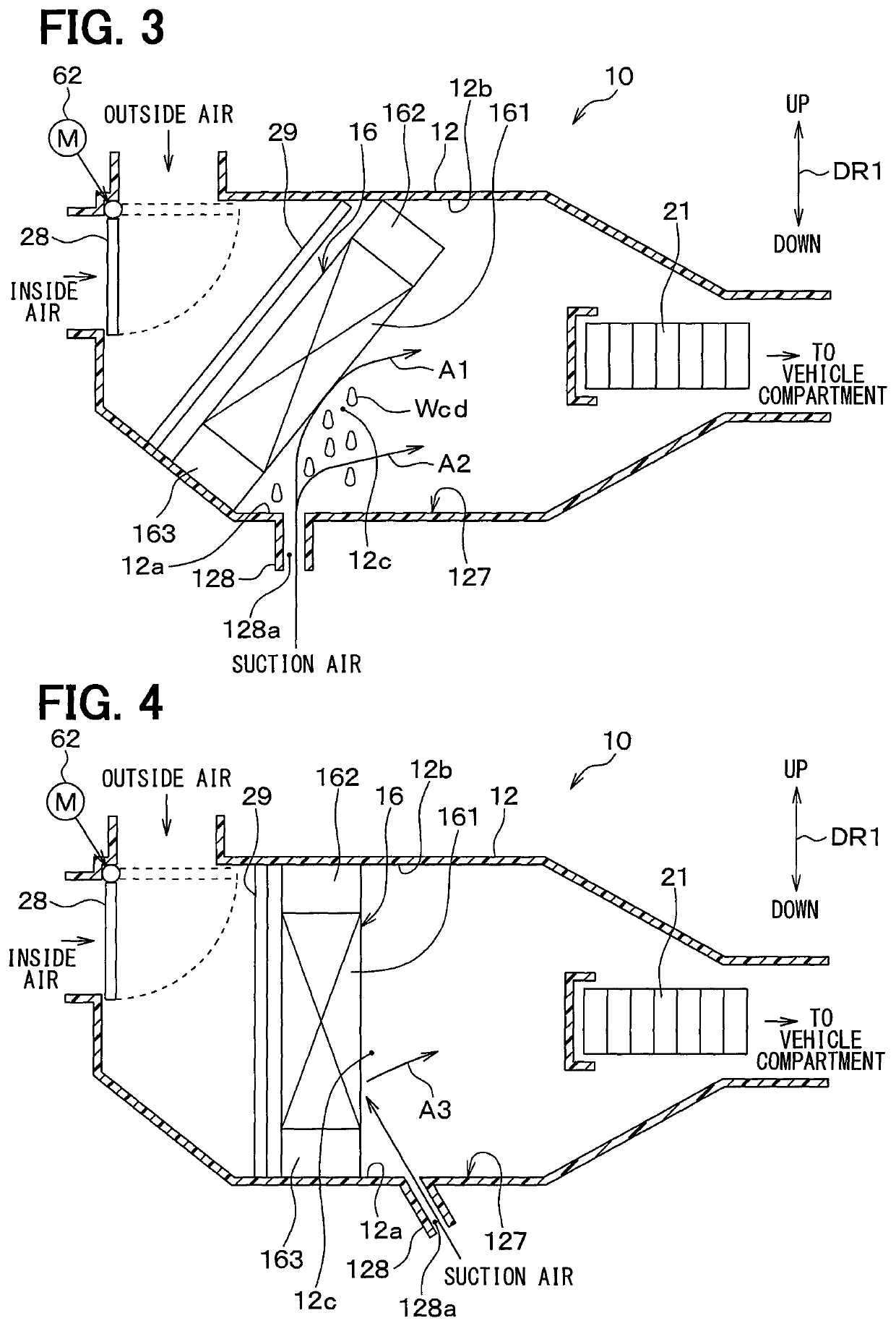
[0052]A vehicle air-conditioning unit 10 according to a second embodiment of the present disclosure will be described referring to FIG. 4. In the vehicle air-conditioning unit 10 of the above-described first embodiment, the evaporator 16 is inclined with respect to the bottom surface 127 of the air-conditioning case 12, and the drain pipe 128 is provided to be perpendicular to the bottom surface 127 of the air-conditioning case 12. In contrast, the vehicle air-conditioning unit 10 of the present embodiment is different from the first embodiment, that is, the evaporator 16 is provided perpendicularly to the bottom surface 127, and the drain pipe 128 is inclined with respect to the bottom surface 127 of the air-conditioning case 12.
[0053]In the present embodiment, an end portion of the evaporator 16 located on an upper side with respect to the vehicle is directly above an end portion located on a lower side with respect to the vehicle. The evaporator 16 is provided such that an air ou...
third embodiment
[0060]A vehicle air-conditioning unit 10 according to a third embodiment of the present disclosure will be described referring to FIG. 5. The vehicle air-conditioning unit 10 of the above-described first embodiment is provided such that the suction air drawn into the air-conditioning case 12 through the drain pipe 128 flows toward the core portion 161 of the evaporator 16. In contrast, the vehicle air-conditioning unit 10 of the present embodiment is provided such that the suction air drawn into the air-conditioning case 12 through the drain pipe 128 flows toward a second header tank portion 163 located on a lower end of the core portion 161 of the evaporator 16. The second header tank portion 163 is included in a half part of the evaporator 16 close to a bottom surface 127 of the air-conditioning case 12. Specifically, the evaporator 16 is arranged such that a centerline of a drain pipe 128 intersects with the second header tank portion 163 located on the lower end of the core port...
PUM
 Abstract
Description
Claims
Application Information
 - R&D
- Intellectual Property
- Life Sciences
- Materials
- Tech Scout
- Unparalleled Data Quality
- Higher Quality Content
- 60% Fewer Hallucinations
Browse by: Latest US Patents, China's latest patents, Technical Efficacy Thesaurus, Application Domain, Technology Topic, Popular Technical Reports.
© 2025 PatSnap. All rights reserved.Legal|Privacy policy|Modern Slavery Act Transparency Statement|Sitemap|About US| Contact US: help@patsnap.com