Supercharge Your Innovation With Domain-Expert AI Agents!

Hybrid workpiece joining

Active Publication Date: 2020-06-16
GM GLOBAL TECH OPERATIONS LLC
View PDF25 Cites 0 Cited by
  • Summary
  • Abstract
  • Description
  • Claims
  • Application Information

AI Technical Summary

Benefits of technology

[0007]Further areas of applicability will become apparent from the description provided herein. It should be understood that the description and specific examples are intended for purposes of illustration only and are not intended to limit the scope of the present disclosure.

Problems solved by technology

A die or mandrel may disrupt a terminal end of the fastener in order to create a mechanical interference between the members and the fastener.
Furthermore, friction caused by the rotation of the fastener against the material assembly generates a heated material zone on the material assembly.

Method used


Image

  • Hybrid workpiece joining
  • Hybrid workpiece joining
  • Hybrid workpiece joining

Examples


Embodiment Construction

[0016]The following description is merely exemplary in nature and is not intended to limit the present disclosure, application, or uses. It should be understood that throughout the drawings, corresponding reference numerals indicate like or corresponding parts and features. Further, directions such as “top,”“side,”“back”, “lower,” and “upper” are used for purposes of explanation and are not intended to require specific orientations unless otherwise stated. These directions are merely provided as a frame of reference with respect to the examples provided, but could be altered in alternate applications.

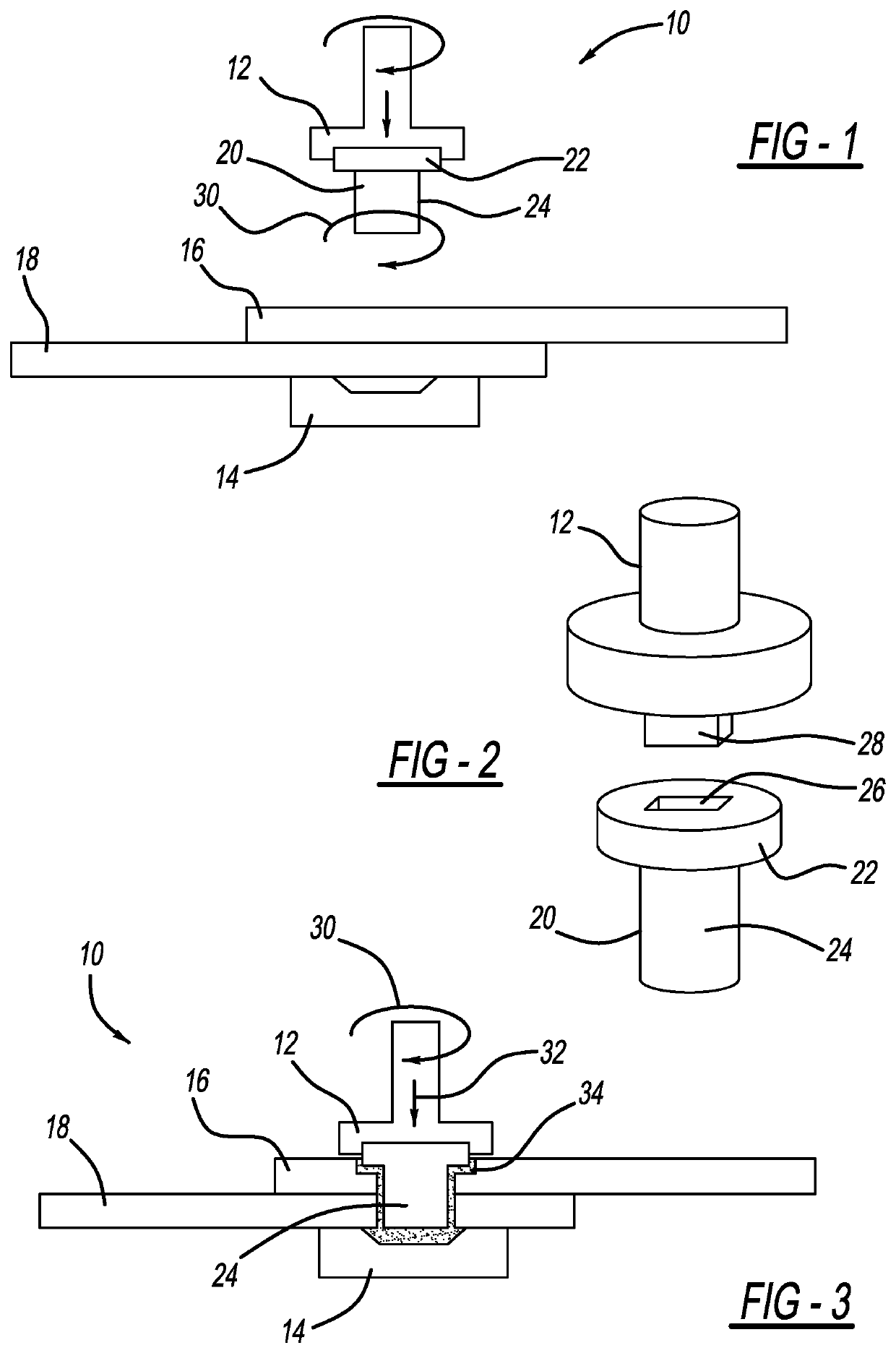
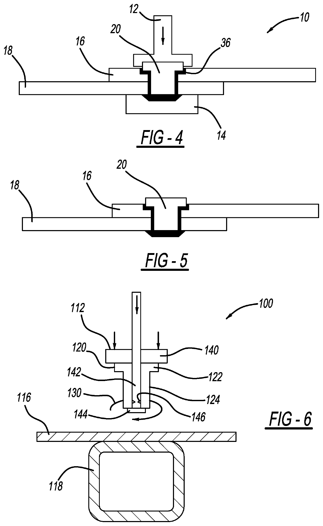
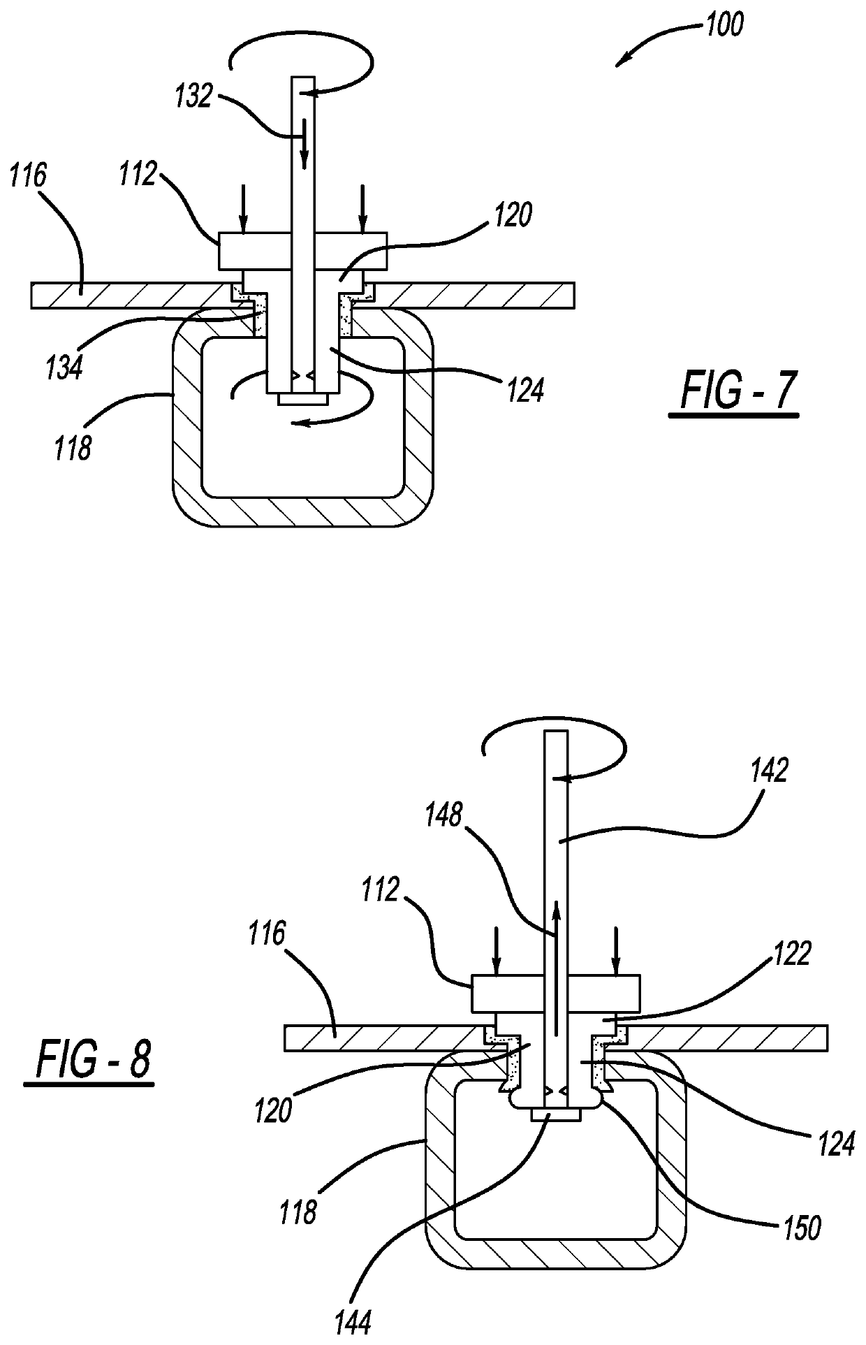
[0017]The present disclosure describes a hybrid technique for joining workpieces, such as polymeric composites, by a combination of friction stir riveting and material fusing. With reference to the drawings, wherein like reference numbers refer to like components, each of the exemplary hybrid joining machines includes a friction stir tool 12 and a lower die 14. The hybrid joining machin...


PUM

PropertyMeasurementUnit
forceaaaaaaaaaa
fractureaaaaaaaaaa
frictionaaaaaaaaaa

Abstract

A method for joining a plurality of workpieces includes providing a rotating drive tool. A fastener is secured to the drive tool. The drive tool is then rotatably driven such that a distal end of the fastener rotates against a surface of the plurality of workpieces. A heated material zone is then generated on the plurality of workpieces as caused by friction from the rotation of the fastener against the surface of the plurality of workpieces. The distal end of the fastener is rotatably and axially driven through the heated material zone. Finally, the drive tool is removed from the fastener, such that when the heated material zone cools, a portion of the heated material zone is fused to the fastener.

Description

FIELD[0001]The present disclosure relates to a workpiece assembly including a fastener and a joining method thereof.INTRODUCTION[0002]The statements in this section merely provide background information related to the present disclosure and may not constitute prior art.[0003]Joining of both ferrous and non-ferrous materials can be achieved through various methods. In one example for joining overlapping members, a fastener can be driven under pressure into the members. A die or mandrel may disrupt a terminal end of the fastener in order to create a mechanical interference between the members and the fastener. In another example for joining overlapping members, an ultrasonic welding device can use high-frequency ultrasonic vibrations to generate heat at an interface of the workpieces. The heated workpieces may melt sufficiently to create a joint at the interface.SUMMARY[0004]A method for joining a plurality of workpieces includes providing a rotating drive tool. A fastener is secured ...

Claims


Application Information

Patent Timeline
Patent Type & Authority Patents(United States)
IPC IPC(8): B23K20/00B21J15/02B21J15/04B23K20/12B23K20/22B23K103/18
CPCB23K20/1295B21J15/027B23K20/22B21J15/043B23K2103/18B21J15/12
Inventor XIAO, GUOXIANGAO, DALONGARINEZ, JORGE F.HUANG, NINGJIANWANG, PEI-CHUNG
Owner GM GLOBAL TECH OPERATIONS LLC
Features
  • R&D
  • Intellectual Property
  • Life Sciences
  • Materials
  • Tech Scout
  • Unparalleled Data Quality
  • Higher Quality Content
  • 60% Fewer Hallucinations
Learn More