Check patentability & draft patents in minutes with Patsnap Eureka AI!

Method for refining molten steel in vacuum degassing equipment

a vacuum degassing and molten steel technology, applied in the field of molten steel refining method, can solve the problems of oxidation loss of manganese, insufficient reduction of increase in carbon concentration in molten steel that has been tapped, so as to promote refining reaction and high yield. , the effect of high yield

Active Publication Date: 2020-08-18
JFE STEEL CORP
View PDF35 Cites 0 Cited by
  • Summary
  • Abstract
  • Description
  • Claims
  • Application Information

AI Technical Summary

Benefits of technology

This approach enhances the yield of added powders and promotes refining reactions, achieving high heat transfer efficiency and productivity in smelting low-carbon high-manganese steel or ultralow-sulfur steel with reduced costs.

Problems solved by technology

However, in case of using these cheap manganese sources, reduction of the manganese ore leads to a failure to lower sufficiently the carbon concentration in molten steel through the decarburization refining in the converter, or the carbon present in high-carbon ferromanganese gives rise to an increase in carbon concentration in the molten steel that has been tapped.
In the vacuum decarburization refining of molten steel containing a large amount of manganese, however, oxygen reacts not only with carbon in the molten steel but also with manganese in the molten steel, with the result that the manganese added is lost by oxidation and the manganese yield is decreased.
Further, the reaction makes it difficult to control the manganese content in the molten steel with good accuracy.
However, it is difficult for the desulfurization at the hot metal stage alone to attain sufficient reduction in sulfur concentration to the desired content of 0.0024 mass % or less for low-sulfur steel or 0.0010 mass % or less for ultralow-sulfur steel.
These methods, however, add a new step (a desulfurization step) between the tapping of steel from a converter and the treatment in vacuum degassing equipment, and thus cause problems such as temperature drop of molten steel, increase in production costs, and decrease in productivity.
However, the approach which involves increasing of the molten steel temperature in a step upstream of the vacuum degassing equipment is accompanied by significant wear and damage of refractory materials in the preceding step, and brings about an increase in cost.
The approach to increasing the temperature by the addition of metallic aluminum in the vacuum degassing equipment is disadvantageous in that, for example, the cleanliness of molten steel is deteriorated due to the resulting aluminum oxide, and the cost of auxiliary materials is increased.
In this type of a refining method, the dynamic pressure of the jet flow ejected from the top blowing lance affects not only the yield of manganese ore and the desulfurization efficiency of the CaO-based desulfurization agent, but also affects the efficiency of heat transfer mediated by the powders.
That is, if the jet flow is ejected from the top blowing lance without appropriate controlling of its dynamic pressure, the effect of the flame cannot be taken advantage of sufficiently.
However, the conventional techniques including those described in Patent Literatures 10, 11 and 12 do not specify the dynamic pressure with which the jet flow is to be ejected from the top blowing lance.

Method used


Image

  • Method for refining molten steel in vacuum degassing equipment

Examples


example 1

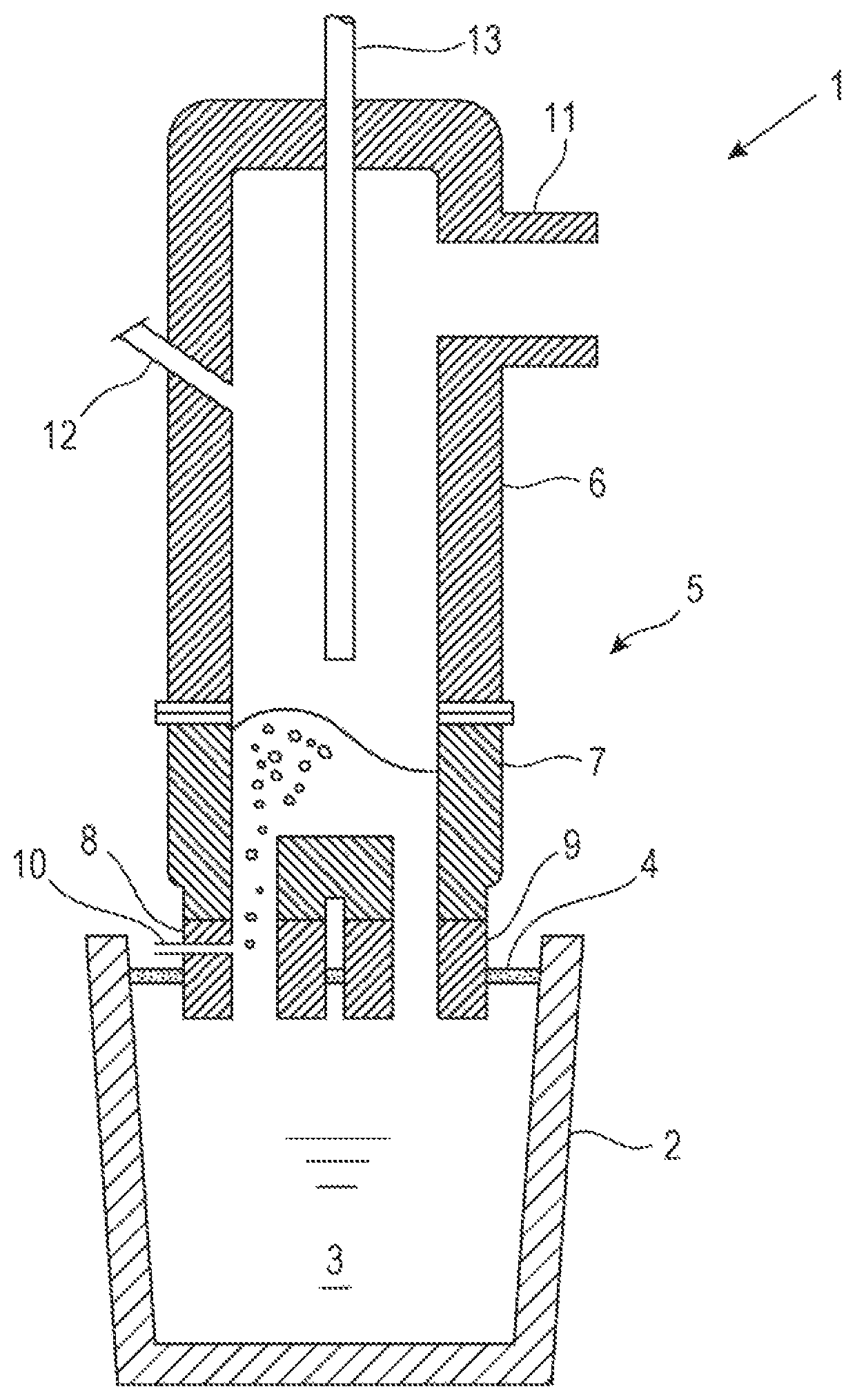
[0075]Tests were carried out in which approximately 300 tons of molten steel was refined by vacuum decarburization with use of an RH vacuum degassing apparatus illustrated in FIG. 1 to smelt low-carbon high-manganese steel.

[0076]The molten steel in the non-deoxidized state as tapped from the converter had a carbon concentration of 0.03 to 0.04 mass % and a manganese concentration of 0.07 to 0.08 mass %. The concentration of dissolved oxygen in the molten steel at the arrival at the RH vacuum degassing apparatus was 0.04 to 0.07 mass %.

[0077]The lance height of the top blowing lance inserted through the top of the vacuum vessel was set to 0.5 to 9.0 m. During the vacuum decarburization refining in the RH vacuum degassing apparatus, LNG (hydrocarbon gas) and oxygen gas (oxygen-containing gas for combusting the hydrocarbon gas) were ejected through the top blowing lance so as to form a burner flame below the leading end of the top blowing lance. After the burner flame had been formed, ...

example 2

[0087]Tests were carried out in which approximately 300 tons of molten steel was desulfurized by the addition of a CaO-based desulfurization agent with use of an RH vacuum degassing apparatus illustrated in FIG. 1 to smelt low-sulfur steel (sulfur concentration: 0.0024 mass % or less).

[0088]The molten steel before refining in the RH vacuum degassing apparatus had a carbon concentration of 0.08 to 0.10 mass %, a silicon concentration of 0.1 to 0.2 mass %, an aluminum concentration of 0.020 to 0.035 mass % and a sulfur concentration of 0.0030 to 0.0032 mass %. The temperature of the molten steel was 1600 to 1650° C.

[0089]Where necessary, the temperature of the molten steel was measured to examine whether the required temperature of the molten steel had been reached before the addition of the CaO-based desulfurization agent. Here, the “required temperature of the molten steel” is the temperature of molten steel determined in each operation depending on the treatment apparatus and treat...


PUM

PropertyMeasurementUnit
heightaaaaaaaaaa
dynamic pressureaaaaaaaaaa

Abstract

A molten steel refining method includes throwing a powder to molten steel while heating the powder with a flame formed by combustion of a hydrocarbon gas at the leading end of a top blowing lance. The lance height of the top blowing lance (the distance between the static bath surface of the molten steel and the leading end of the lance) is controlled to 1.0 to 7.0 m, and the dynamic pressure P of a jet flow ejected from the top blowing lance calculated from equation (1) below is controlled to 20.0 kPa or more and 100.0 kPa or less. P=ρg× U2 / 2 . . . (1) wherein P is the dynamic pressure (kPa) of the jet flow at an exit of the top blowing lance, ρg the density (kg / Nm3) of the jet flow, and U the velocity (m / sec) of the jet flow at the exit of the top blowing lance.

Description

TECHNICAL FIELD[0001]The present disclosure relates to a molten steel refining method for smelting low-carbon high-manganese steel, low-sulfur steel, ultralow-sulfur steel or the like by throwing (blowing) powders such as manganese ore and CaO-based desulfurization agent to a bath surface of the molten steel under vacuum in vacuum degassing equipment from a top blowing lance while heating the powders with a flame formed at the leading end of the top blowing lance.BACKGROUND ART[0002]Recently, iron steel materials have gained use in diversified applications and have come to be frequently used in harsher environments than ever. Associated with this fact, demands on properties such as mechanical characteristics of steel products also have become severer than before. Under these circumstances, low-carbon high-manganese steel which possesses high strength and high workability has been developed for purposes of increasing strength of structural objects and reducing weight and cost thereof...

Claims


Application Information

Patent Timeline
Patent Type & Authority Patents(United States)
IPC IPC(8): C21C7/10C21C7/04C21C7/068C21C7/00C21C7/072C21C7/064
CPCC21C7/064C21C7/068C21C7/072C21C7/04C21C7/0037C21C7/0645C21C7/10
Inventor FUJII, YUSUKENAKAI, YOSHIEKIKUCHI, NAOKISHIBUTA, NAOYANAGAI, SHINICHIMAEDA, TAKAHIKOMIKI, YUJI
Owner JFE STEEL CORP
Features
  • R&D
  • Intellectual Property
  • Life Sciences
  • Materials
  • Tech Scout
  • Unparalleled Data Quality
  • Higher Quality Content
  • 60% Fewer Hallucinations
Learn More