Check patentability & draft patents in minutes with Patsnap Eureka AI!

Cell separation chip and system

a cell separation and chip technology, applied in the field of cell separation systems and methods, can solve the problems of difficult to accurately analyze cancer cells, low success probability of initial detection of cancer cells in blood, and still relatively expensive systems for separating cancer cells from blood, so as to improve the reuse efficiency of cell separation systems and improve the accuracy of coupling. the effect of setting and accuracy

Active Publication Date: 2020-09-01
GENOBIO CORP
View PDF24 Cites 0 Cited by
  • Summary
  • Abstract
  • Description
  • Claims
  • Application Information

AI Technical Summary

Benefits of technology

This design enhances the accuracy and efficiency of cancer cell separation, reduces costs by allowing for easy replacement and reuse of components, and simplifies the installation process while maintaining consistent flow rates and minimizing contamination.

Problems solved by technology

For this reason, the likelihood of success of initial detection of cancer cells in blood is substantially low.
Cancer cells are difficult to accurately analyze due to the presence of interfering factors such as contaminants and air bubbles during analysis.
In addition, systems for separating cancer cells from blood are still relatively expensive given that the number of cancer patients is rapidly increasing every year.
In addition to this economic burden, the systems are complicated to install.
However, this patent document fails to consider the problems of contamination during injection of the blood sample and inaccurate separation of cancer cells.
However, this patent document fails to consider technical details for securing preset values for flow channels during discharge and the same amount and rate of substances flowing through the flow channels.
At this time, the flow rate of the cancer cells in each flow channel may vary depending on the length and height of the channel, causing poor separation accuracy.

Method used


Image

  • Cell separation chip and system
  • Cell separation chip and system
  • Cell separation chip and system

Examples


first embodiment

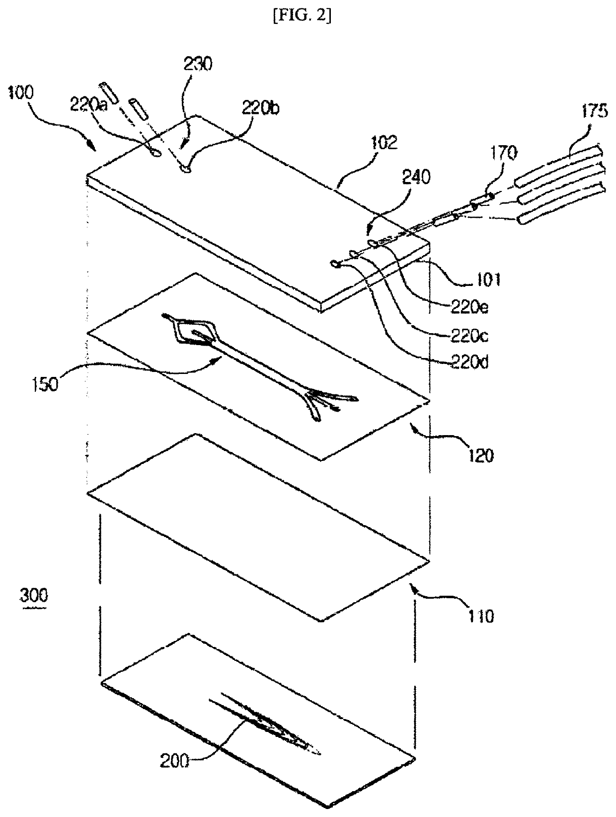
[0028]FIG. 2 illustrates a separation chip 30 according to one embodiment of the present invention.

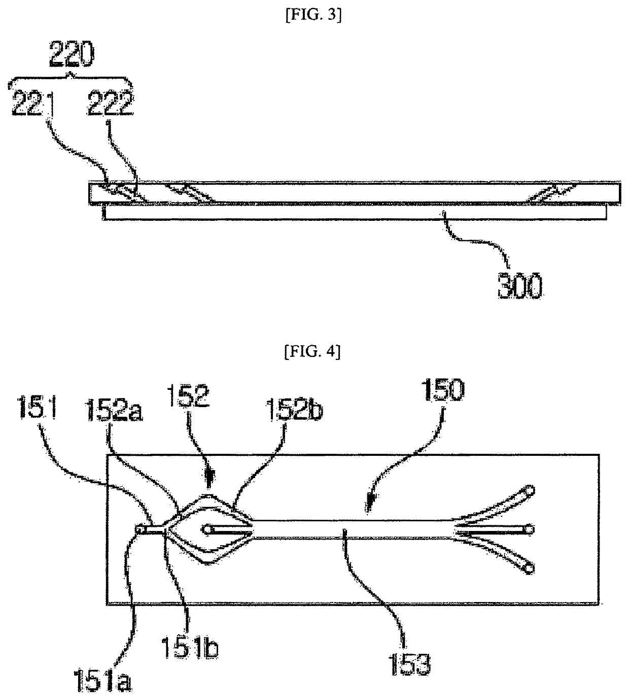
[0029]FIG. 3 illustrates the construction of holes of a separation chip 30 according to one embodiment of the present invention.

[0030]FIG. 4 illustrates a first embodiment of channels of a separation chip 30 according to one embodiment of the present invention.

second embodiment

[0031]FIG. 5 illustrates channels of a separation chip 30 according to one embodiment of the present invention.

third embodiment

[0032]FIG. 6 illustrates channels of a separation chip 30 according to one embodiment of the present invention.

[0033]FIG. 7 illustrates the locations of filters on channels of a separation chip 30 according to one embodiment of the present invention.

[0034]FIG. 8 illustrates the construction of filters of a separation chip 30 according to one embodiment of the present invention.

[0035]FIG. 9 is a top cross-sectional view of a base plate according to one embodiment of the present invention.

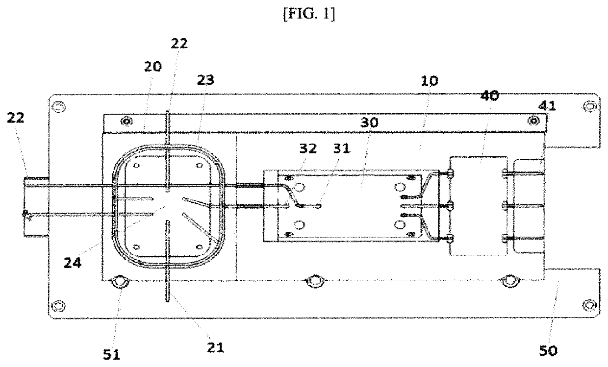
[0036]FIG. 10 is a cross-sectional view illustrating an arrangement in which a cell separation cartridge and a base plate are fixed to each other according to one embodiment of the present invention.

[0037]FIG. 11 illustrates a structure in which a cell separation cartridge is fixed to a base plate according to one embodiment of the present invention.

[0038]FIG. 12 illustrates a structure in which a separation chip 30 on a cartridge is coupled to a magnetic chip on a base plate.


PUM

PropertyMeasurementUnit
angleaaaaaaaaaa
shapeaaaaaaaaaa
acute anglesaaaaaaaaaa

Abstract

The present invention relates to a system and method for cell separation. The system includes: a cartridge having a polygonal shape in cross section and including an injection part, a separation chip separating a flow channel of a sample injected through the injection part, and a discharge part; and a base plate coupled to the cartridge through its upper surface and including a magnetic chip for cancer cell capture, liquid sensors, and valves. The method includes: coupling a cut plane of one side of the cell separation cartridge to one side of the base plate; engaging a recess formed at the other end of the cell separation cartridge with a pin formed at the other end of the base plate; fixing holes of the separation chip of the cell separation cartridge and holes of the magnetic chip of the base plate using a fixing member to match the holes of the separation chip of the cell separation cartridge and the holes of the magnetic chip of the base plate; and determining whether a pattern of the separation chip of the cell separation cartridge matches a pattern of the magnetic chip of the base plate.

Description

CROSS-REFERENCE TO RELATED APPLICATIONS[0001]This application is the U.S. National Phase under 35 U.S.C. § 371 of International Application No. PCT / KR2016 / 015502 filed on Dec. 29, 2016, which in turn claims the benefit of Korean Applications No. 10-2016-0019173, filed on Feb. 18, 2016 and No. 10-2016-0182071, filed on Dec. 29, 2016, the disclosures of which are incorporated by reference into the present application.TECHNICAL FIELD[0002]The present invention relates to a system and method for cell separation. More specifically, the present invention relates to a system for cell separation in which an injection part and a separation part necessary for cell separation are provided on the same cartridge so that they can be coupled to and separated from each other by one-time operation and accurate coupling of the cell separation cartridge to a base plate can be easily checked, and a method for cell separation using the system.BACKGROUND ART[0003]27.9% of all deaths in Korea in 2015 resu...

Claims


Application Information

Patent Timeline
Patent Type & Authority Patents(United States)
IPC IPC(8): B01L3/00G01N35/00G01N33/574G01N35/08
CPCG01N35/08G01N35/00G01N33/574B01L3/502761B01L3/502776B01L2400/043B01L2300/087B01L2300/0816B01L2300/088B01L2300/0864B01L2300/0877B01L2200/0652
Inventor LEE, JEA KUHWANG, JU HYUNPARK, SUNG HOONJO, JONG JIN
Owner GENOBIO CORP
Features
  • R&D
  • Intellectual Property
  • Life Sciences
  • Materials
  • Tech Scout
  • Unparalleled Data Quality
  • Higher Quality Content
  • 60% Fewer Hallucinations
Learn More