Check patentability & draft patents in minutes with Patsnap Eureka AI!

Isolation amplifier

an isolation amplifier and amplifier technology, applied in the direction of amplifiers, voltage/current isolation, electrical apparatus, etc., can solve the problems of not being able to change the operation or a subsequent calibration of a fully encapsulated device, and the calibration of such an isolation amplifier at high input voltage is very time-consuming, so as to achieve the effect of shortening the delivery tim

Active Publication Date: 2020-09-08
KNICK ELEKTRONISCHE MESSGERATE
View PDF14 Cites 0 Cited by
  • Summary
  • Abstract
  • Description
  • Claims
  • Application Information

AI Technical Summary

Benefits of technology

Enables fully encapsulated devices to be calibrated and parameterized on demand, maintaining uncompromised high-voltage insulation and addressing changes in transmission characteristics due to environmental and aging effects, reducing delivery times and ensuring safety and efficiency.

Problems solved by technology

In contrast, commercially available so-called optocouplers are rather unsuitable for the transmission of electrical energy.
A change in the operation or a subsequent calibration of a fully encapsulated device is then no longer possible without weakening the isolation or, in some cases, even without damage to the isolation.
A calibration of such an isolation amplifier at high input voltages is very time-consuming due to the configuration and calibration interface being arranged on the input side.
This places high demands on the insulation of test and calibration devices.
Generally speaking therefore, it is apparent that due to the incomplete encapsulation of an isolation amplifier according to the prior art described above, the isolation of the high-voltage input side is weakened.

Method used


Image

  • Isolation amplifier
  • Isolation amplifier
  • Isolation amplifier

Examples


Embodiment Construction

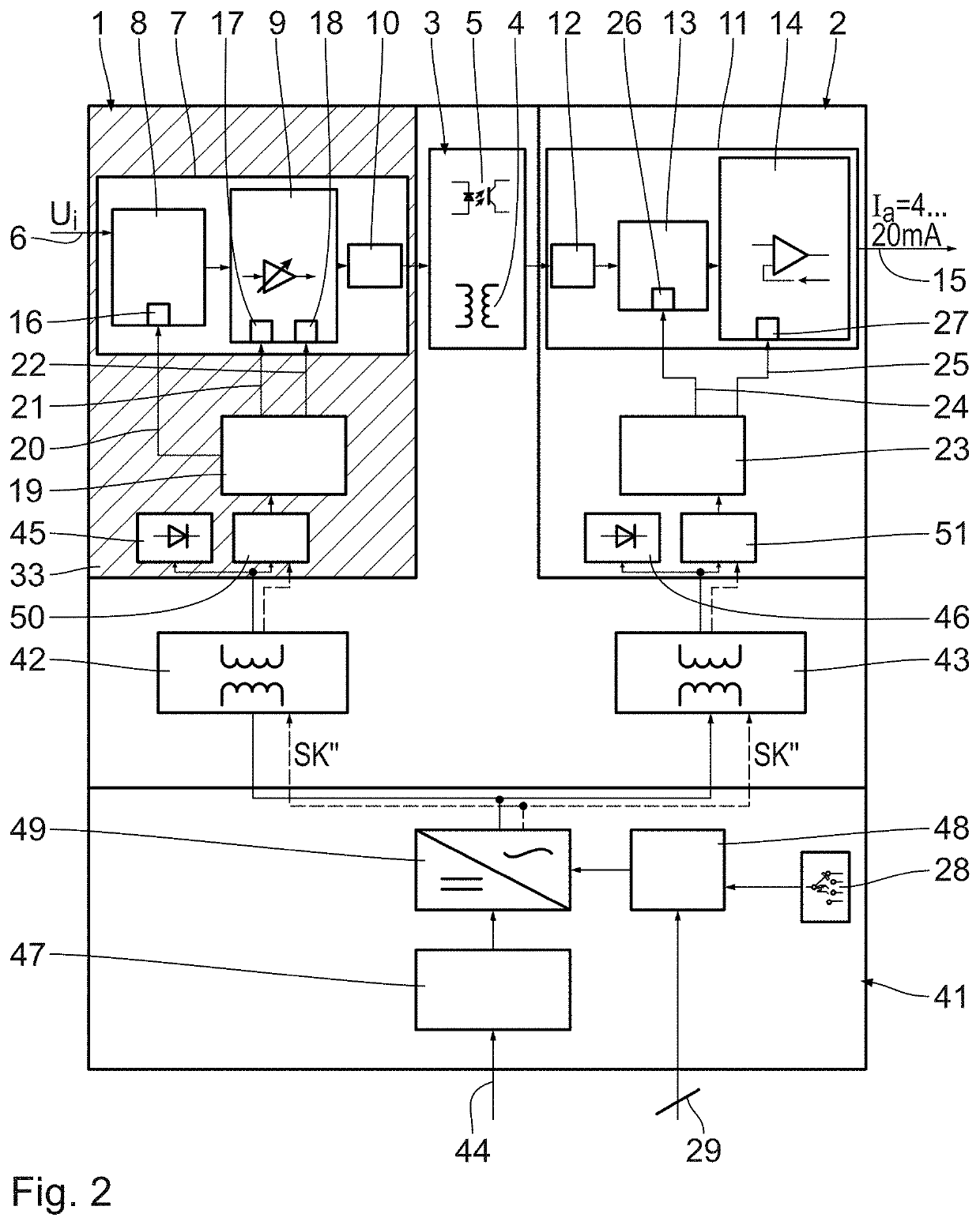
[0042]FIG. 1 shows a high-voltage isolation amplifier with an input circuit 1 at high-voltage potential and an output circuit 2 at low-voltage potential, wherein the two circuits are connected by a galvanically isolating coupling section 3 for potential-free transmission of a coupling section signal (which represents the measurement signal). As an example of the coupling section 3 the drawing shows only two possible alternatives, namely an inductively coupling transformer 4 and an opto-coupler 5.

[0043]The input circuit 1 has an input 6 at high-voltage potential, for example, to which, for example, a voltage signal Ui in the high-voltage range can be supplied as the parameter to be measured. Downstream of the input 6 is an input circuit labeled as a unit with 7, which comprises an input network 8 with a selectable current and voltage input, a pre-amplifier 9 for the measurement signal Ui to be transmitted and to be processed in the input network 8, and a modulator 10 for providing th...


PUM


Abstract

An isolation amplifier includes an input circuit at high voltage potential with an input for a measurement signal to be transmitted, an input circuit configuration providing a coupling section signal representing the measurement signal, and a high-voltage-side control unit for driving the input circuit, a galvanically isolating coupling section for the potential-free transmission of the coupling section signal to an output circuit at low-voltage potential with an output circuit configuration for generating an output signal from the transmitted coupling section signal, an output for the output signal and at least one low-voltage-side control unit for generating control signals, input elements for inputting control commands and / or parameters into the high-voltage-side control unit, a low-voltage-side arrangement of all the input elements provided for the parameterization of the high-voltage-side control unit, exclusively in a low-voltage circuit, and a galvanically isolating control channel for transmitting the parameters for driving the input circuit.

Description

CROSS-REFERENCE TO RELATED APPLICATIONS[0001]This application claims the priority of German patent application Serial No. DE 10 2016 214 263.1, filed on Aug. 2, 2016, pursuant to 35 U.S.C. 119 (a)-(d), the content thereof being incorporated herein by reference in its entirety as if fully set forth herein.FIELD OF THE INVENTION[0002]The invention relates to an isolation amplifier comprising an input circuit at high voltage potential having an input for a measurement signal to be transmitted, an input circuit for providing a coupling section signal representing the measurement signal, and a high-voltage-side control unit for driving the input circuit configuration, a galvanically isolating coupling section for the potential-free transmission of the coupling section signal to an output circuit at high-voltage potential having an output circuit for generating an output signal representing the measurement signal from the transmitted coupling section signal, an output for the output signa...

Claims


Application Information

Patent Timeline
Patent Type & Authority Patents(United States)
IPC IPC(8): H03F3/38H03F3/387G01R15/22G01R15/18G01R15/20H03F3/68H03G3/02
CPCH03F3/38H03F3/387H03F3/68G01R15/22G01R15/20G01R15/18H03G3/02H03F2200/228H03F2200/171H03F2200/276H03F2200/375H03F2200/273
Inventor BACHUS, KLAUSZANK, HARALD
Owner KNICK ELEKTRONISCHE MESSGERATE
Features
  • R&D
  • Intellectual Property
  • Life Sciences
  • Materials
  • Tech Scout
  • Unparalleled Data Quality
  • Higher Quality Content
  • 60% Fewer Hallucinations
Learn More