Supercharge Your Innovation With Domain-Expert AI Agents!

Condition monitoring system

a technology of condition monitoring and monitoring system, which is applied in the direction of testing/monitoring control system, process and machine control, etc., can solve the problems of putting high constraints on the reliability of communication within the monitoring system, and limiting the monitoring system, so as to improve the processing of condition related data

Active Publication Date: 2020-09-15
AB SKF
View PDF13 Cites 0 Cited by
  • Summary
  • Abstract
  • Description
  • Claims
  • Application Information

AI Technical Summary

Benefits of technology

[0007]The present invention is based on the realization that it may be possible to improve processing of condition related data by time stamping parameters relating to the rotation of a shaft of the rotating system, and distribute that information over a network to e.g. monitoring devices where further processing may be done.
[0008]In the proposed implementation, data from a sensor configured for providing indications of a rotation of the shaft is time stamped and arranged in a format suitable for distribution over a network, where at least one further electronic device, such as a monitoring device, may receive the information and include it in further calculations. Advantages includes the possibility to in a more generic way share the rotational related information between a large plurality of electronic devices, e.g. including monitoring devices, without having to resort to complicated wiring and amplifiers which is commonly used in prior art monitoring systems when rotational related information is distributed to more than one further electronic device or over a larger distance. Rather, according to the invention it may be possible to use an already available network, wired or wireless, for distributing the rotational related information.
[0013]Advantageously, the monitoring device may be configured to comprise a buffer for storing a plurality of parameters from the second sensor. By including a buffer with the monitoring device it is possible to handle possible network related delays when transmitting data packages between the measurement and the monitoring device. The buffer may possibly be arranged to dynamically adjust its size depending on previously identified network delays.
[0015]Alternatively, it may also be possible to instead, or also, measure an operational temperature of an element of the rotating system, a torque level of the shaft of the rotating system, a current of a motor or a generator connected to the shaft of the rotating system. More specifically, within the scope of the present invention, any dynamic signal that may make use of accurate measurements relating to the rotation of the shaft of the rotating system may be correlated with the rotational related data from the tachometer arranged in vicinity of the shaft of the rotating system. Still further, the second sensor may e.g. be a second tachometer sensor arranged at a distance from the first sensor and thereby allowing for determining a possible torsion of the shaft of the rotating system.

Problems solved by technology

Even though the monitoring technique disclosed in US2011 / 0020122 A1 provides a promising approach for reducing down time in a wind turbine, the use of a centralized controller puts high constraints on the reliability of communication within the monitoring system for securing essential real-time processing of the condition information.
Such an approach will for example place limitations on the monitoring system in case future up-scaling of the system is desirable.

Method used


Image

  • Condition monitoring system
  • Condition monitoring system
  • Condition monitoring system

Examples


Embodiment Construction

[0024]The present invention will now be described more fully hereinafter with reference to the accompanying drawings, in which currently preferred embodiments of the invention are shown. This invention may, however, be embodied in many different forms and should not be construed as limited to the embodiments set forth herein; rather, these embodiments are provided for thoroughness and completeness, and fully convey the scope of the invention to the skilled addressee. Like reference characters refer to like elements throughout.

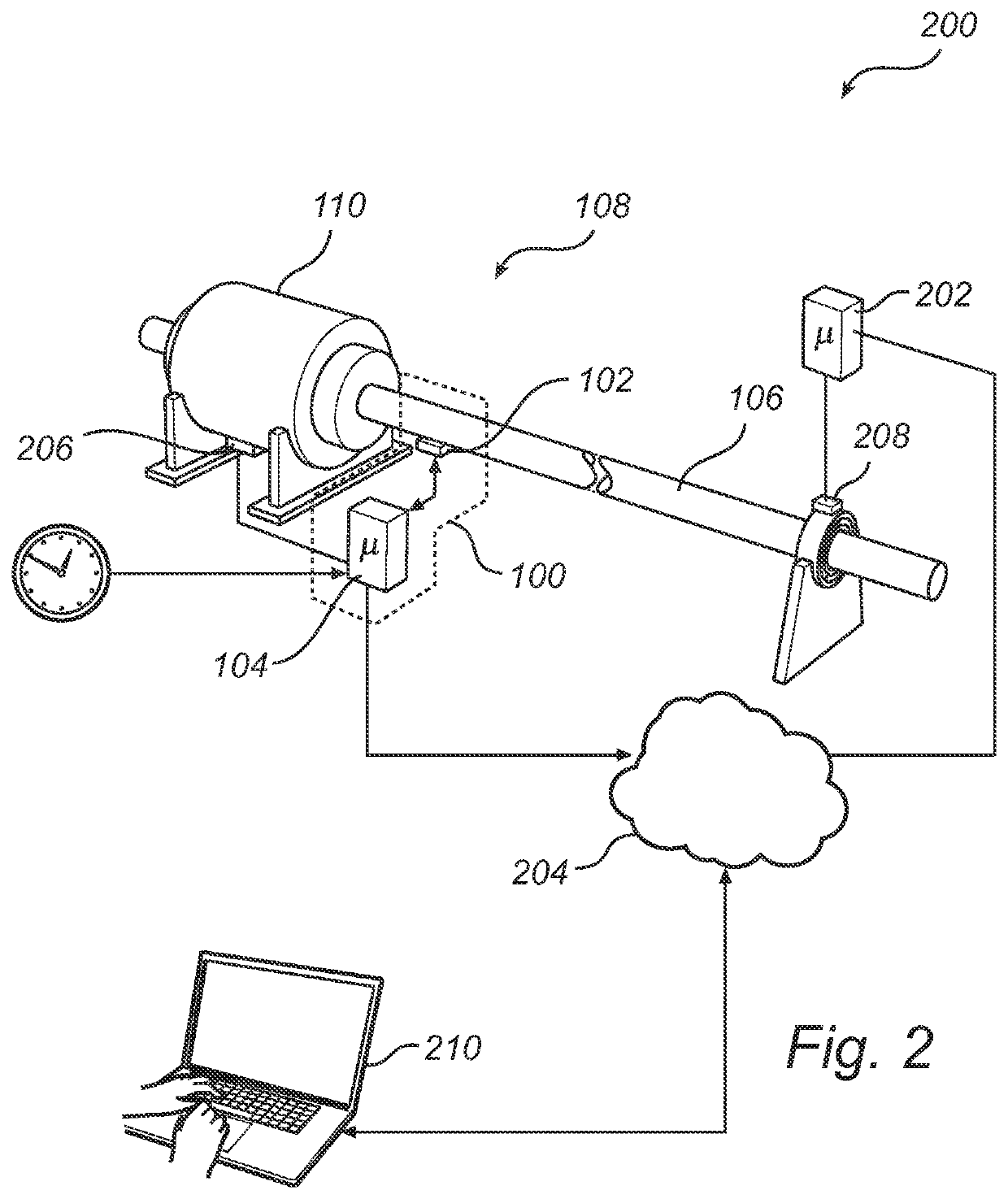
[0025]Turning now to the drawings and to FIG. 1 in particular, it is schematically illustrated a measurement device 100 according to an embodiment of the invention. The measurement device 100 comprises a tachometer 102 and a control unit 104 configured to receive sensor data from the tachometer 102. In FIG. 1 the measurement device 100 is arranged to measure the rotational speed (or angle of rotation) of a shaft 106 of a rotating system 108, the rotating system...


PUM


Abstract

The present invention relates to a measurement device for a rotating system, the measurement device providing a first sensor arranged in the vicinity of a shaft of the rotating system, the first sensor being configured to generate a signal relating to a rotation of the shaft, and a control unit connected to the first sensor. The control unit is further configured to form a first parameter based on the signal from the first sensor, determine a current time reference, form a data package having the first parameter and a time stamp relating to the current time reference, and distribute the data package to at least one monitoring device over a network connected to the control unit. The present invention also relates to a monitoring system having the measurement device and a corresponding method for monitoring a condition of a rotating system.

Description

CROSS-REFERENCE[0001]This application is the US national stage of International Application No. PCT / SE2013 / 000023 filed on Feb. 18, 2013, which claims priority to Swedish Patent Application No. 1200122-8 filed Feb. 27, 2012.FIELD OF THE INVENTION[0002]The present invention generally relates to condition monitoring of a rotating system, specifically to improved analysis performed by a monitoring system based on a time stamped signal from a tachometer.TECHNICAL BACKGROUND[0003]Condition monitoring is widely applied to determine a current and possible future status of mechanical machinery, including for example rotational systems such as turbines, generators, railway, and other industry processing equipment. Generally, data relating to temperature, rotation, vibration, etc, is analyzed for determining a change in operation, possibly initiating predictive maintenance of the rotating system for securing a long lifetime as well as reducing down time in case of equipment failure. There exi...

Claims


Application Information

Patent Timeline
Patent Type & Authority Patents(United States)
IPC IPC(8): G01M13/00G01P3/00
CPCG01M13/00G01P3/00G05B23/024
Inventor SUNDQUIST, FREDRIK
Owner AB SKF
Features
  • R&D
  • Intellectual Property
  • Life Sciences
  • Materials
  • Tech Scout
  • Unparalleled Data Quality
  • Higher Quality Content
  • 60% Fewer Hallucinations
Learn More