Supercharge Your Innovation With Domain-Expert AI Agents!

Method for forming a functionalised assembly guide

a functionalised and assembly guide technology, applied in the field of functionalised assembly guide formation, can solve the problems of difficult control of secondary pattern orientation, detrimental to transfer, residual layer, etc., and achieve the effect of not allowing the possibility of selecting the affinity of the side walls of the cavity

Active Publication Date: 2020-09-22
COMMISSARIAT A LENERGIE ATOMIQUE ET AUX ENERGIES ALTERNATIVES
View PDF9 Cites 0 Cited by
  • Summary
  • Abstract
  • Description
  • Claims
  • Application Information

AI Technical Summary

Benefits of technology

This method allows for precise control of the chemical affinities of the side walls relative to the bottom, enhancing the control over block copolymer interactions and enabling the formation of assembly guides with cavities that can withstand higher temperatures, thus improving the resolution and stability of the patterns formed.

Problems solved by technology

It is often difficult to control the orientation of the secondary patterns relative to a guide pattern.
Yet this residual layer is detrimental for the transfer, into the substrate, of holes obtained by the selective etching of the PMMA phase.
This technique does not allow the possibility of selecting the affinity of the side walls of the cavities, because this is dictated by the material of which the cavity is made.
The use of a resin to form the assembly guide does not always allow the possibility of selecting the affinity of the side walls of the cavities, because this is dictated by the chemistry of the resin.
Thus, control of the interactions with the block copolymer deposited in the cavities will be limited in this method of the prior art.
Besides, the resin has poor thermal resistance which reduces the possibilities of annealing for the assembly of the block copolymer or implies dimensional variations of the assembly guide (the sides made of resin of the assembly guide are deformed on heating).

Method used


Image

  • Method for forming a functionalised assembly guide
  • Method for forming a functionalised assembly guide
  • Method for forming a functionalised assembly guide

Examples


Embodiment Construction

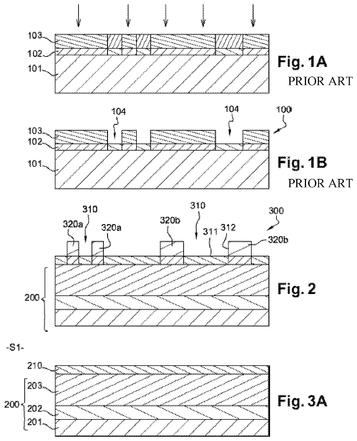
[0057]With reference to FIG. 2, the method according to the invention makes it possible to obtain on the surface of a substrate 200 a functionalised assembly guide 300 comprising one or more cavities 310. Each cavity 310 is intended to be filled with a block copolymer in order to form therein at least one secondary pattern of high resolution, by directed self-assembly of the block copolymer. The bottom 311 of the cavities 310 is functionalised in such a way as to have a first chemical affinity with regard to the block copolymer, whereas the side walls 312 of the cavities are functionalised so as to have a second chemical affinity with regard to the block copolymer. The side walls 312 of the cavities extend, preferably, perpendicularly to the plane of the substrate 200.

[0058]The cavities 310 of the assembly guide 300 may adopt different geometries. They may notably take the shape of a cylindrical well, a rectangular or elliptical well, a trench or any other shape suited to graphoepit...


PUM

PropertyMeasurementUnit
depthaaaaaaaaaa
depthaaaaaaaaaa
thicknessaaaaaaaaaa

Abstract

A method for forming a functionalised assembly guide intended for the self-assembly of a block copolymer by graphoepitaxy, includes forming on the surface of a substrate a neutralisation layer made of a first material having a first neutral chemical affinity with regard to the block copolymer; forming on the neutralisation layer a first mask including at least one recess; depositing on the neutralisation layer a second material having a second preferential chemical affinity for one of the copolymer blocks, in such a way as to fill the at least one recess of the first mask; and selectively etching the first mask relative to the first and second materials, thereby forming at least one guide pattern made of the second material arranged on the neutralisation layer.

Description

CROSS REFERENCE TO RELATED APPLICATIONS[0001]This application is the U.S. National Stage of PCT / FR2017 / 052890, filed Oct. 20, 2017, which in turn claims priority to French Patent Application No. 1660231 filed Oct. 21, 2016, the entire contents of all applications are incorporated herein by reference in their entireties.TECHNICAL FIELD[0002]The present invention relates to a method for forming a functionalised assembly guide intended for the self-assembly of a block copolymer. The present invention also relates to a graphoepitaxy method using a functionalised assembly guide obtained by such a method.PRIOR ART[0003]The need for methods making it possible to produce patterns of nanometric dimensions has increased considerably over recent years, on account of the tendency towards miniaturisation of electronic components.[0004]Among emerging lithography technologies, it is possible to cite techniques of directed self-assembly (DSA) of block copolymers. Block copolymers are polymers in wh...

Claims


Application Information

Patent Timeline
Patent Type & Authority Patents(United States)
IPC IPC(8): H01L21/033G03F7/00H01L21/02H01L21/027H01L21/3105H01L21/311B81C1/00H01L21/308
CPCB81C1/00031H01L21/3086H01L21/31111H01L21/0338H01L21/31144H01L21/3088H01L21/0271H01L21/0337G03F7/0002H01L21/02118B81C1/00388H01L21/31055B81C2201/0149G03F7/004G03F7/2012H01L21/027H01L21/304H01L21/30604H01L21/3065
Inventor CLAVEAU, GUILLAUMEARGOUD, MAXIMEPOSSEME, NICOLASTIRON, RALUCA
Owner COMMISSARIAT A LENERGIE ATOMIQUE ET AUX ENERGIES ALTERNATIVES
Features
  • R&D
  • Intellectual Property
  • Life Sciences
  • Materials
  • Tech Scout
  • Unparalleled Data Quality
  • Higher Quality Content
  • 60% Fewer Hallucinations
Learn More