Supercharge Your Innovation With Domain-Expert AI Agents!

Diaphragm arrangement for a planar dynamic sound transducer, and methods to produce therefor

a dynamic transducer and diaphragm technology, applied in the direction of electrical transducers, loudspeakers, electrical apparatus, etc., can solve the problems of transfer resistances having measurable negative effects, conductor tracks can already be damaged or pierced, and the thin metal layer produced is too fragile to achieve a secure and very low-resistance connection

Active Publication Date: 2020-10-27
SENNHEISER ELECTRONICS GMBH & CO KG
View PDF13 Cites 1 Cited by
  • Summary
  • Abstract
  • Description
  • Claims
  • Application Information

AI Technical Summary

Benefits of technology

This method provides a more reliable and efficient electrical connection with reduced system resistance and mass, improving the overall performance and durability of planar dynamic sound transducers by avoiding damage to the conductor tracks and eliminating the need for complex contacting methods.

Problems solved by technology

Electrical contacting of those coated track structures is not a trivial matter as the metallic layers produced are too thin and fragile to achieve a secure and very low-resistance connection directly for example by soldering or bonding.
In contrast to electrostatic or capacitive sound transducers, in the case of planar dynamic systems the overall resistance is generally relatively low, for example in the region of between 16 and 50 Ohms, which has the result that transfer resistances can have measurable negative effects.
With this structure however the conductor track can already be damaged or pierced by very small irregularities and unevenness.
The described contacting by pressing the part on the conductor track can be adversely affected thereby.
In addition there is the risk that in the course of time the contact pressing pressure drops off due to vibration, shaking, material shrinkage and fatigue and so forth, or moisture in the air or other substances pass due to capillary forces between the contact surfaces and cause them to be corroded or fouled.
In any of those cases contact resistances occur, which worsen the efficiency of the sound transducer as far as complete failure due to an interruption.
Such conductive viscous material however generally involve a lower level of conductivity than metals, whereby the degree of efficiency is reduced.
In addition the sometimes complex chemical composition of those substances can be problematic in relation to long-term stability of the electric connection.

Method used


Image

  • Diaphragm arrangement for a planar dynamic sound transducer, and methods to produce therefor
  • Diaphragm arrangement for a planar dynamic sound transducer, and methods to produce therefor
  • Diaphragm arrangement for a planar dynamic sound transducer, and methods to produce therefor

Examples


Embodiment Construction

[0029]It is to be understood that the figures and descriptions of the present invention have been simplified to illustrate elements that are relevant for a clear understanding of the present invention, while eliminating, for purposes of clarity, many other elements which are conventional in this art. Those of ordinary skill in the art will recognize that other elements are desirable for implementing the present invention. However, because such elements are well known in the art, and because they do not facilitate a better understanding of the present invention, a discussion of such elements is not provided herein.

[0030]The present invention will now be described in detail on the basis of exemplary embodiments.

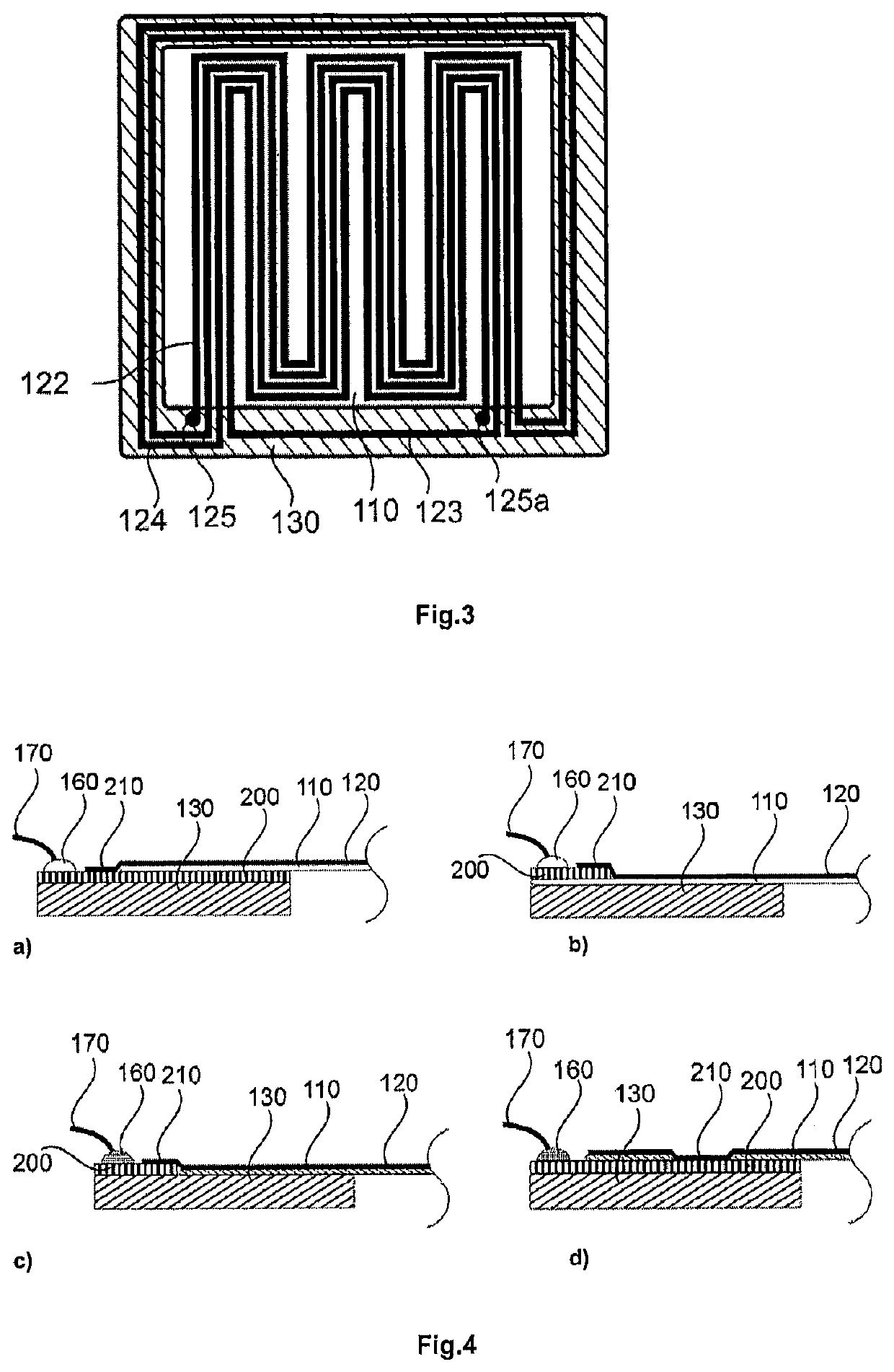
[0031]FIG. 4 shows the basic principle of direct contacting of conductor tracks applied by coating, in various variants. In this case the diaphragm film of the sound transducer is coated during the layer production step by coating with an electrically conductive material as far...


PUM


Abstract

A planar dynamic sound transducer includes a magnet arrangement which for example comprises bar magnets and a fixing frame, and a diaphragm arrangement. The diaphragm arrangement has a tensioned diaphragm film (diaphragm for short), a tensioning device for the diaphragm, and a conductor structure applied to the diaphragm. When the conductor structure is conventionally provided with electrical connections mechanically sensitive connections and / or high transfer resistances often occur. An improved diaphragm arrangement for a planar dynamic sound transducer includes a support frame having at least one contacting surface, and a diaphragm tensioned on the support frame, and which at least one electrically conductive conductor track is applied by coating. At least one end of the conductor track applied by coating extends on to the contacting surface of the support frame. The connecting line can be connected to the contacting surface of the support frame by way of a solder join.

Description

[0001]The present application claims priority from International Patent Application No. PCT / EP2018 / 051059 filed on Jan. 17, 2018, which claims priority from German Patent Application No. DE 10 2017 102 219.8 filed on Feb. 6, 2017, the disclosures of which are incorporated herein by reference in their entirety.FIELD OF THE INVENTION[0002]It is noted that citation or identification of any document in this application is not an admission that such document is available as prior art to the present invention.[0003]The invention concerns a planar dynamic transducer, in particular a planar dynamic sound transducer.[0004]Planar dynamic sound transducers usually comprise a magnet arrangement having a plurality of magnet bars arranged in parallel and a diaphragm, wherein the plane of the magnet arrangement is parallel to the plane of the diaphragm. In operation for sound reproduction an electric current flows through a flat coil mounted directly on the diaphragm, wherein a deflection force is...

Claims


Application Information

Patent Timeline
Patent Type & Authority Patents(United States)
IPC IPC(8): H04R9/04H04R7/04H04R7/18H04R9/02H04R9/06H04R1/06
CPCH04R7/04H04R9/06H04R9/025H04R9/047H04R7/18H04R2400/11H04R1/06H04R2209/024
Inventor JACQUES, ROLAND
Owner SENNHEISER ELECTRONICS GMBH & CO KG
Features
  • R&D
  • Intellectual Property
  • Life Sciences
  • Materials
  • Tech Scout
  • Unparalleled Data Quality
  • Higher Quality Content
  • 60% Fewer Hallucinations
Learn More