Check patentability & draft patents in minutes with Patsnap Eureka AI!

Tie-down assembly

a technology of tie-down and assembly, which is applied in the direction of transportation items, load transportation vehicles, vehicles, etc., can solve the problems of bending or breaking, limited strength of d-rings,

Active Publication Date: 2020-11-10
MCDERMOTT CHAD
View PDF2 Cites 0 Cited by
  • Summary
  • Abstract
  • Description
  • Claims
  • Application Information

AI Technical Summary

Benefits of technology

The solution provides a stronger and more compact tie-down assembly that effectively secures heavy loads without interfering with the truck bed's horizontal plane, ensuring secure and unobstructed use.

Problems solved by technology

While useful, the D-ring is limited in strength and therefore can bend or break when a heavy load is secured.

Method used


Image

  • Tie-down assembly
  • Tie-down assembly

Examples


Embodiment Construction

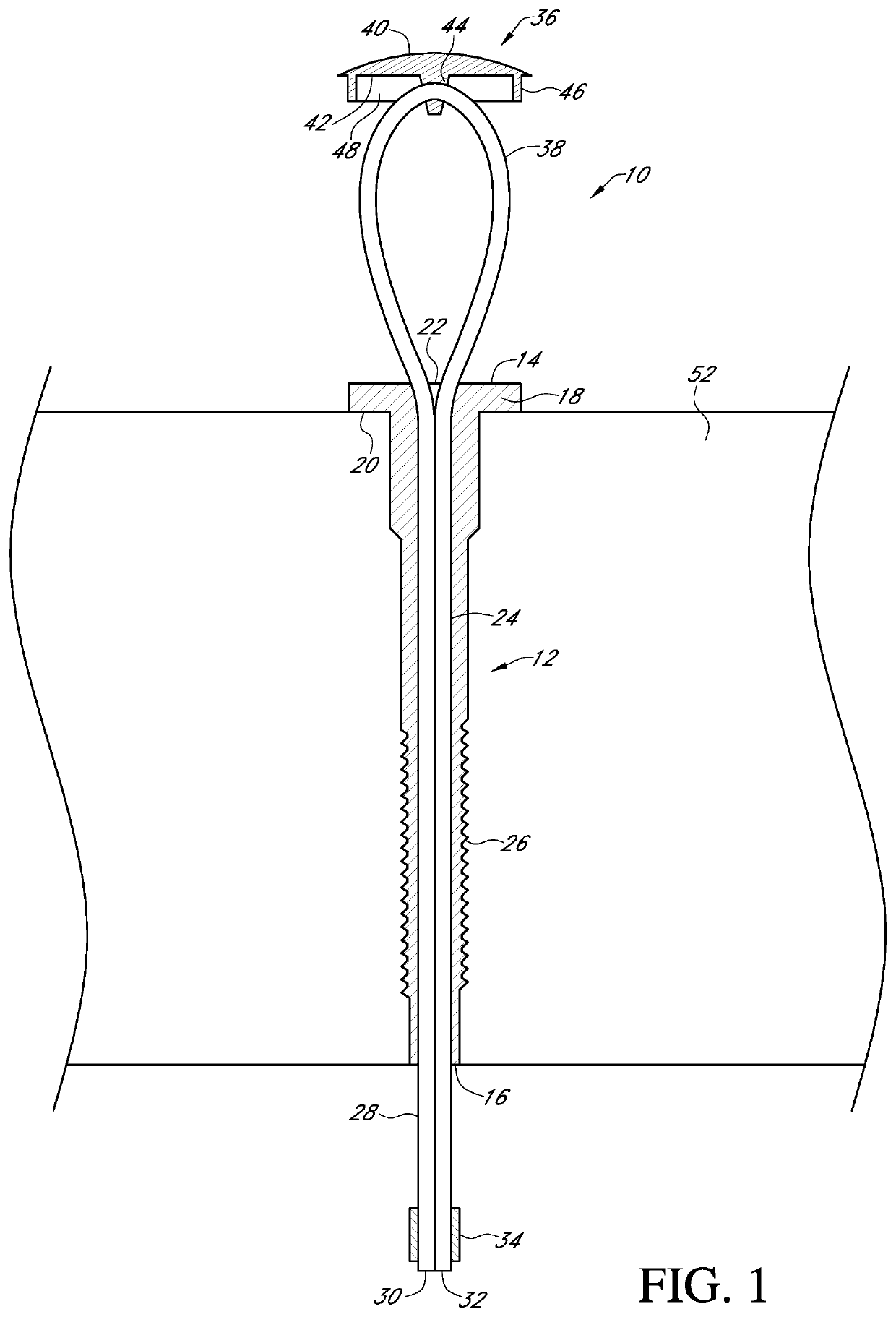
[0013]Referring to the Figures a tie-down assembly 10 includes a hollow elongated tube or member 12 having a first end 14 and a second end 16. The tie-down assembly can be used in any application where an object needs to be secured. For purposes of example only the tie-down assembly is disclosed in reference to use with a bed of a pick-up truck. Attached to the first end 14 of the elongated member 12 is a head 18. The head 18 is either integrally molded or welded to the elongated member 12. The head 18 also is transverse to the elongated member 12 and extends radially outwardly from the elongated member 12 to form a shoulder 20. The head 18 has a central opening 22 in alignment with a bore 24 of the elongated member 12. An outer surface 26 of the elongated member 12 is preferably threaded.

[0014]Disposed through the bore 24 of the elongated member 12 and extending outwardly from the first and second ends 14 and 16 is a cable 28, rope or the like. The cable 28 has a first end 30 and a...


PUM


Abstract

A tie-down assembly includes a hollow elongated member, a cable, and a cover. The cable is threaded through the hollow elongated member and threaded through an eyelet in the cover. From the eyelet, the cable is threaded back through the hollow elongated member to form a loop. Once threaded, the ends of the cable are joined with a stop.

Description

CROSS REFERENCE TO RELATED APPLICATION[0001]This application claims the benefit of U.S. Provisional Application No. 62 / 672,127 filed on May 16, 2018, the contents of these applications are hereby incorporated by reference in their entirety.BACKGROUND OF THE INVENTION[0002]This invention is directed to a tie-down assembly and more particularly to a tie-down assembly for securing a load to an anchoring member such as the bed of a pick-up truck or the like.[0003]Tie-down assemblies are known in the art. In one example a D-ring is attached to the head of a bolt and the bolt attached to the bed of a pick-up. While useful, the D-ring is limited in strength and therefore can bend or break when a heavy load is secured. Other tie-down assemblies have a profile that interferes with the horizontal plane of the truck bed. Accordingly, there exists a need in the art for a device that addresses these deficiencies.[0004]An objective of the present invention is to provide a tie-down assembly with g...

Claims


Application Information

Patent Timeline
Patent Type & Authority Patents(United States)
IPC IPC(8): B60P7/08
CPCB60P7/0807B60P7/08
Inventor MCDERMOTT, CHAD NOLAN
Owner MCDERMOTT CHAD
Features
  • R&D
  • Intellectual Property
  • Life Sciences
  • Materials
  • Tech Scout
  • Unparalleled Data Quality
  • Higher Quality Content
  • 60% Fewer Hallucinations
Learn More