Check patentability & draft patents in minutes with Patsnap Eureka AI!

Trapezoidal CMP groove pattern

a groove pattern and groove technology, applied in the field of grooves, can solve the problems of limited improvement in polishing, shortening the life of the pad, and substantial increase in the use of slurry

Active Publication Date: 2020-12-08
ROHM & HAAS ELECTRONICS MATERIALS CMP HLDG INC
View PDF60 Cites 0 Cited by
  • Summary
  • Abstract
  • Description
  • Claims
  • Application Information

AI Technical Summary

Benefits of technology

The proposed pad design enhances removal rate, extends pad life, reduces defects, and improves edge profiles by optimizing slurry distribution and debris removal, enabling higher downforce and precision polishing with reduced heat and temperature issues.

Problems solved by technology

The disadvantage of this groove pattern is that it provides limited improvement in polishing with a substantial increase in slurry usage and shorter pad life due to less landing area on the polishing pad.

Method used


Image

  • Trapezoidal CMP groove pattern
  • Trapezoidal CMP groove pattern
  • Trapezoidal CMP groove pattern

Examples


Embodiment Construction

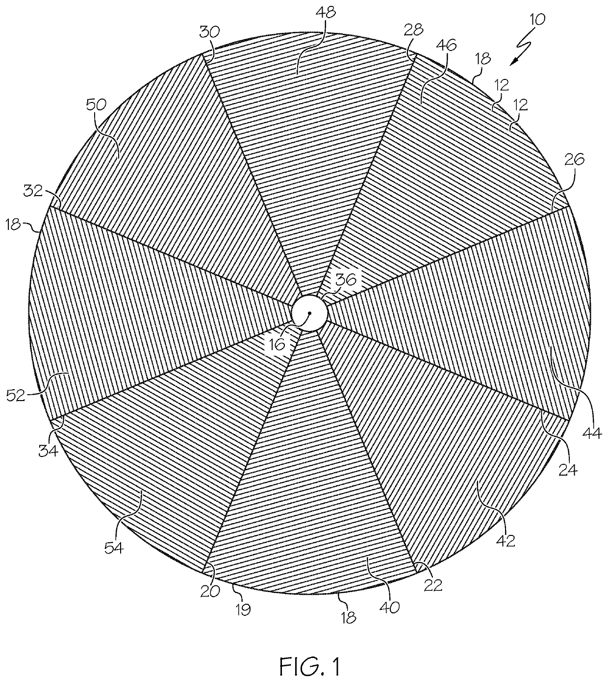
[0047]The groove pattern and method of the invention provide for controlled and uniform distribution of polishing fluids, such as abrasive-containing slurries and abrasive-free polishing solutions. The efficient distribution allows the user to decrease slurry flow in comparison to conventional grooves. Furthermore the interconnected groove path allows polishing debris to leave the pad in an efficient manner for lowering polishing defects. Finally, the groove pattern improves polishing uniformity, wafer profile, die scale uniformity and can improve edge effects.

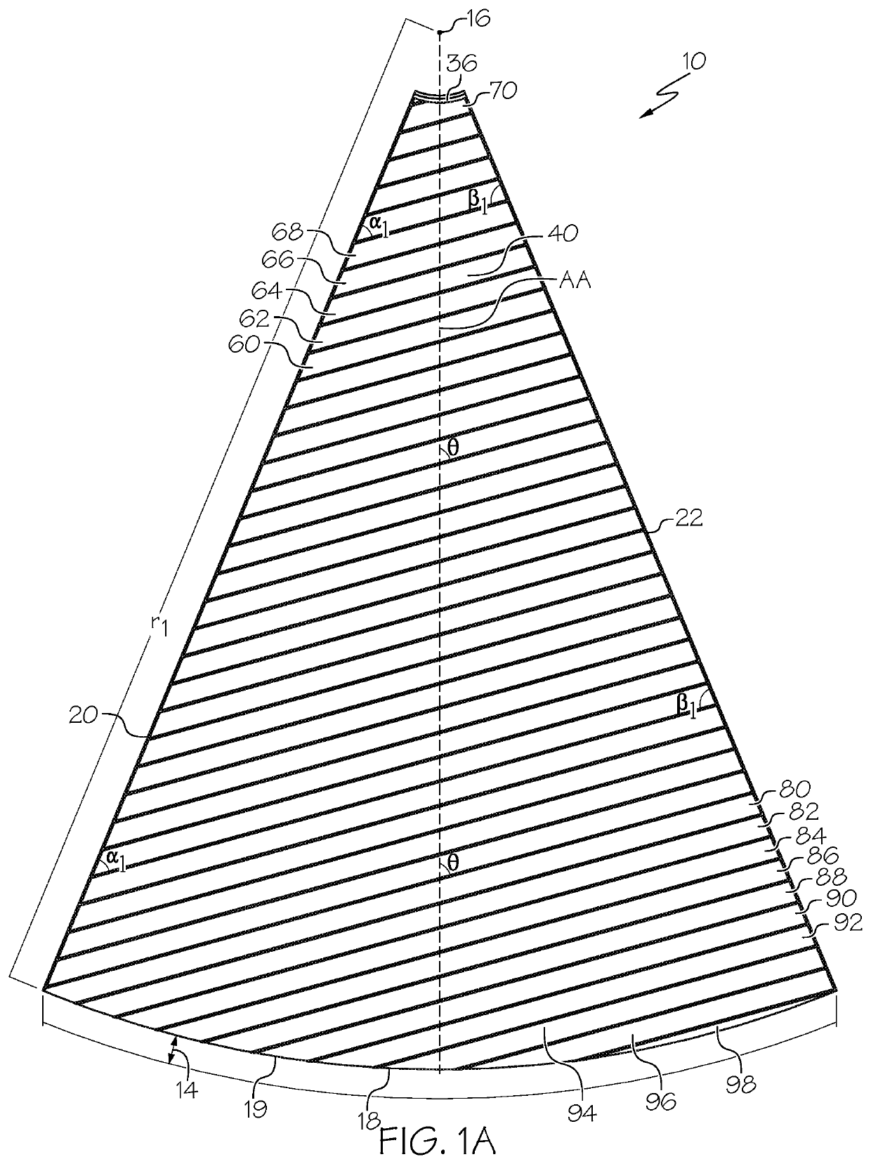
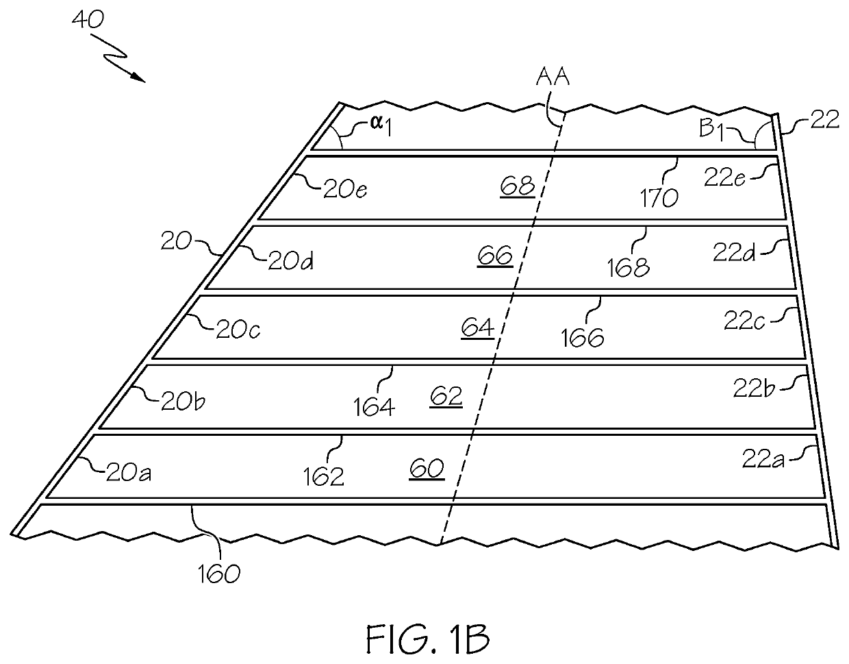
[0048]The term “trapezoid” as used herein and in the claims means interconnected grooves forming a quadrilateral or four-sided shape having only one pair of parallel sides. The trapezoid has two parallel base sides and two legs connecting the base sides. All angles of the trapezoid add up to 360°.

[0049]The term “non-isosceles trapezoid” as used herein and in the claims means interconnected grooves forming a trapezoid having tw...


PUM


Abstract

The polishing pad is suitable for polishing or planarizing a wafer of at least one of semiconductor, optical and magnetic substrates. The polishing pad includes a polishing layer having a polymeric matrix and radial feeder grooves in the polishing layer separating the polishing layer into polishing regions. The radial feeder grooves extend at least from a location adjacent the center to a location adjacent the outer edge of the polishing pad. Each polishing region includes a series of spaced non-isosceles trapezoid groove structures having parallel base segments connecting two adjacent radial feeder grooves to form leg segments. The series of non-isosceles trapezoid groove structures extend from adjacent the outer edge toward the center of the polishing pad with the perimeter of the series of trapezoid structures also being a trapezoid.

Description

CROSS-REFERENCE TO RELATED APPLICATIONS[0001]This is a continuation-in-part application of U.S. Ser. No. 15 / 624,908, filed Jun. 16, 2017, now pending, which was a continuation-in-part application of U.S. Ser. No. 15 / 623,221, filed Jun. 14, 2017, now pending.BACKGROUND[0002]The present invention relates to grooves for chemical mechanical polishing pads. More particularly, the present invention relates to groove designs for increasing removal rate, improving global uniformity and reducing defects during chemical mechanical polishing.[0003]In the fabrication of integrated circuits and other electronic devices, multiple layers of conducting, semiconducting and dielectric materials are deposited onto and removed from a surface of a semiconductor wafer. Thin layers of conducting, semiconducting and dielectric materials may be deposited using a number of deposition techniques. Common deposition techniques in modern wafer processing include physical vapor deposition (PVD), also known as spu...

Claims


Application Information

Patent Timeline
Patent Type & Authority Patents(United States)
IPC IPC(8): B24B37/26H01L21/306
CPCB24B37/26H01L21/30625H01L21/304H01L21/31051H01L21/32115H01L21/76819H01L21/7684
Inventor NGUYEN, JOHN VUTRAN, TONY QUANHENDRON, JEFFREY JAMESSTACK, JEFFREY ROBERT
Owner ROHM & HAAS ELECTRONICS MATERIALS CMP HLDG INC
Features
  • R&D
  • Intellectual Property
  • Life Sciences
  • Materials
  • Tech Scout
  • Unparalleled Data Quality
  • Higher Quality Content
  • 60% Fewer Hallucinations
Learn More