Supercharge Your Innovation With Domain-Expert AI Agents!

Lens-measuring machine and lens-measurement method

a technology of measuring machine and lens, which is applied in the direction of mechanical measuring arrangement, optical apparatus testing, instruments, etc., can solve the problems of deteriorating measurement accuracy, difficult to measure the surface profile of such lenses with high accuracy, and complicating the structure and control of the machine used for the profile measurement method. , to achieve the effect of easy measurement, high accuracy and easy measurement of the lens profil

Active Publication Date: 2021-02-16
MITUTOYO CORP
View PDF17 Cites 0 Cited by
  • Summary
  • Abstract
  • Description
  • Claims
  • Application Information

AI Technical Summary

Benefits of technology

This approach enables highly accurate and easy measurement of lens profiles with reduced contact tip area, using standard roundness measuring machines and simplifying data processing, thereby improving measurement precision and ease of operation.

Problems solved by technology

Some of aspheric lenses (e.g. wide-angle lenses) have recently come to exhibit a large offset from a reference spherical surface, making it difficult to measure the surface profile of such lenses with high accuracy.
Thus, the measurement accuracy is greatly affected by the sphericity of the contact tip 401, resulting in deterioration in the measurement accuracy.
However, the profile measuring method disclosed in Patent Literature 2, which inclines the stylus in conformity with the first or second half of the surface of the one side of the lens, complicates the structure and control of the machine used for the profile measuring method.
In addition, since the two measurement data with different coordinate systems have to be stitched, the data processing becomes complicated.

Method used


Image

  • Lens-measuring machine and lens-measurement method
  • Lens-measuring machine and lens-measurement method
  • Lens-measuring machine and lens-measurement method

Examples


Embodiment Construction

)

[0054]Exemplary embodiment(s) of the invention will be described below with reference to the attached drawings.

Lens-Measuring Machine

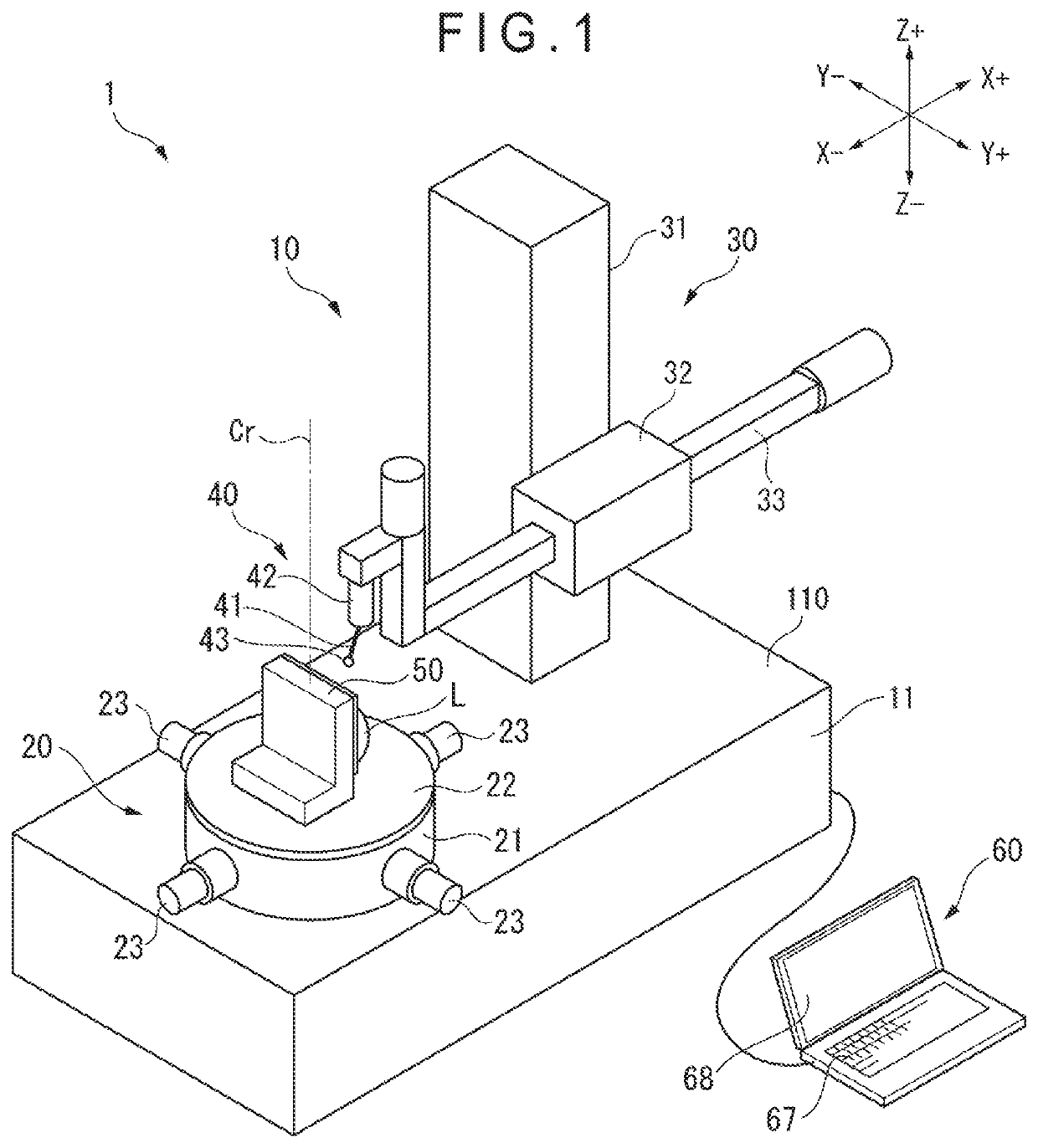
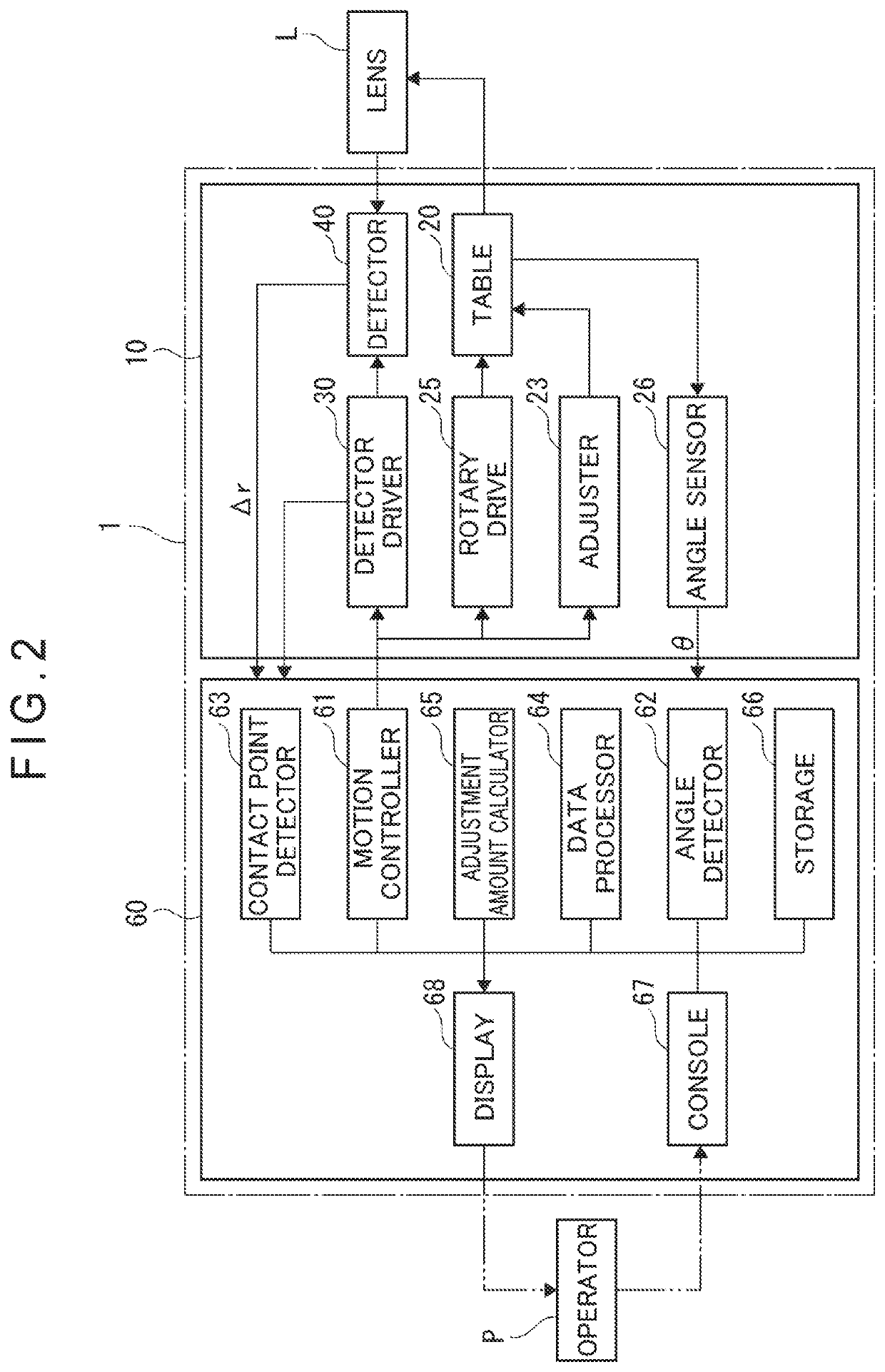
[0055]As shown in FIG. 1, a lens-measuring machine 1 includes a measuring machine body 10, and a controller 60 configured to control the movement of the measuring machine body 10 and to import and process measurement data obtained by the measuring machine body 10.

[0056]An existing roundness measuring machine is usable as the measuring machine body 10.

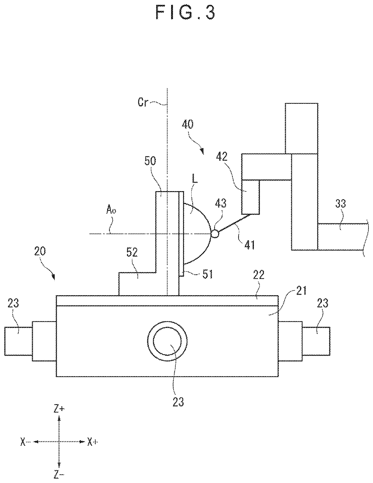
[0057]Specifically, the measuring machine body 10 includes: a base 11; a table 20 provided on an upper face 110 of the base 11; a detector driver 30 provided near the table 20; and a detector 40 supported by the detector driver 30.

[0058]The table 20 is rotated by a rotary drive 25 (see FIG. 2) provided in the table 20. The table 20 is placed so that a rotation axis Cr of the table 20 is aligned with a vertical direction (Z-axis direction) on the upper face 110 of the base 11. An angle sensor 26 (see FIG. ...


PUM


Abstract

A lens-measuring machine includes: a table rotatable around a rotation axis; a lens holder that holds a workpiece in a form of a lens, the lens holder being placed on the table so that an optical axis of the lens becomes orthogonal to the rotation axis; a contact tip that contacts a measurement surface of the lens; an angle sensor for detecting a rotary angle of the table; a displacement detector for detecting a displacement of the contact tip; and a controller for calculating coordinates information of the measurement surface of the lens in a form of polar coordinates, whose origin is at the rotation axis, based on displacement of the contact tip for every predetermined rotary angle of the table, the controller converting the calculated polar coordinates into Cartesian coordinates.

Description

[0001]The entire disclosure of Japanese Patent Application No. 2018-002686 filed Jan. 11, 2018 is expressly incorporated by reference herein.TECHNICAL FIELD[0002]The present invention relates to a lens-measuring machine and a lens-measurement method for measuring a lens profile.BACKGROUND ART[0003]Surface profiles of lenses requiring high profile accuracy have been typically measured using a contact profile-measuring machine. For instance, Patent Literature 1 (JP-2010-164532 A) discloses that a linear movement profile measuring machine is used to perform a contact-scanning measurement of a surface of a lens to determine a cross-sectional profile of the lens.[0004]Some of aspheric lenses (e.g. wide-angle lenses) have recently come to exhibit a large offset from a reference spherical surface, making it difficult to measure the surface profile of such lenses with high accuracy. It should be noted that the “offset” herein is a difference between the spherical surface and an actual surfa...

Claims


Application Information

Patent Timeline
Patent Type & Authority Patents(United States)
IPC IPC(8): G01B5/008G01B5/20G01M11/08
CPCG01B5/008G01B5/20G01M11/08G01B21/04G01M11/025
Inventor OMORI, YOSHIYUKI
Owner MITUTOYO CORP
Features
  • R&D
  • Intellectual Property
  • Life Sciences
  • Materials
  • Tech Scout
  • Unparalleled Data Quality
  • Higher Quality Content
  • 60% Fewer Hallucinations
Learn More