Supercharge Your Innovation With Domain-Expert AI Agents!

3D pattern cutting machine for lithium metal electrode

a lithium metal electrode and 3d pattern technology, which is applied in the manufacturing process of electrodes, cell components, electrochemical generators, etc., can solve the problems of reducing the capacity of the battery, reducing and so as to improve the productivity of the lithium metal electrode. , the effect of reducing the cost and time of 3d pattern replacement and cleaning

Active Publication Date: 2021-05-11
LG ENERGY SOLUTION LTD
View PDF45 Cites 1 Cited by
  • Summary
  • Abstract
  • Description
  • Claims
  • Application Information

AI Technical Summary

Benefits of technology

The solution enables cost-effective and efficient production of lithium metal unit electrodes with consistently formed 3D patterns, reducing the time and cost associated with pattern replacement and improving the uniformity of dendrite growth inhibition, thereby enhancing battery life and safety.

Problems solved by technology

However, there are the following problems in applying the lithium metal to the negative electrode.
Since the polymer electrolyte is chemically very active, the passive film is formed by reaction with the organic electrolyte, and as oxidation (dissolution) and reduction (deposition) reactions of lithium on the lithium metal surface during charging and discharging are repeated unevenly, the formation and growth of the passive film is extremely severe.
As a result, not only the capacity of the battery is reduced during charging and discharging but also as the charging and discharging process is repeated, lithium ions are grown in the form of needles on the surface of the lithium metal to thereby form a dendrite (lithium resin phase), which shortens the life of the battery, resulting in short circuit between the electrodes.
As described above, the lithium metal has a capacity of about 3860 mAh / g per unit weight, but it is difficult to commercialize it due to the continuous reaction with the electrolyte in the battery and the resinous growth of lithium due to its life.
However, in this case, there is a problem that the rollers themselves have to be replaced if desiring to engrave different kinds of patterns.
The bigger problem is that the rollers used in the rolling process are generally made of metal because they have to be heavily weighted to maintain a constant pressure, and thus an issue of releasing from lithium metal occurs.
Lithium metal is a very fragile metal.
Therefore, when rolling with a metal roller, it tends to stick to the roller.

Method used


Image

  • 3D pattern cutting machine for lithium metal electrode
  • 3D pattern cutting machine for lithium metal electrode
  • 3D pattern cutting machine for lithium metal electrode

Examples


example 1

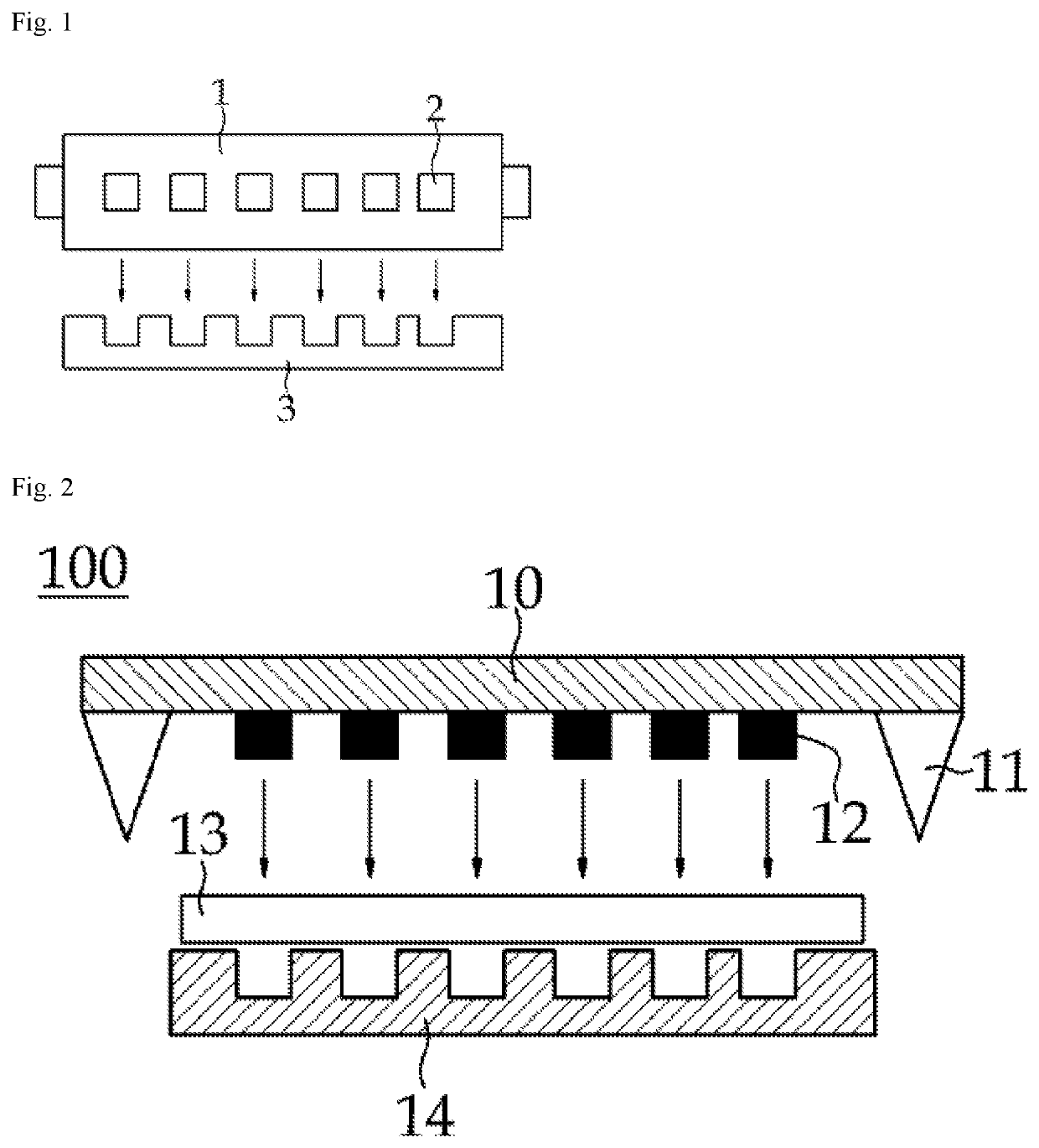
[0056]A metal mold punch having a 3D pattern mold having a cubic 3D pattern of a size of 20 μm×20 μm×20 μm (width×breadth×depth) was prepared. The material of the 3D pattern mold was polyurethane acrylate. A lithium metal electrode having a thickness of 100 μm was placed on the die. While pushing down the punching mold from the top down, a 3D pattern was engraved on the surface of the lithium metal electrode and punched out. The punched lithium metal unit electrode was released from the mold, and the mold punch was moved up and down while continuously supplying the lithium metal electrode through the roller-type unwinder on the side of the die, thereby preparing 10 lithium metal unit electrodes.

example 2

[0057]A lithium metal unit electrode was prepared in the same manner as in Example 1 except that a 3D pattern mold having a semi-spherical 3D pattern with a diameter of 20 μm was attached.

example 3

[0058]The lithium metal unit electrode has been manufactured in the same manner as Example 1 except that the punch mold and 3D pattern integrally use a mold made of polyurethane acrylate.


PUM

PropertyMeasurementUnit
depthaaaaaaaaaa
densityaaaaaaaaaa
depthaaaaaaaaaa

Abstract

A 3-dimensional (3D) pattern puncher for punching a lithium metal electrode to provide one or more unit electrodes is provided. The 3D pattern puncher includes a mold punch configured to move up and down, the mold punch corresponding to a size of the unit electrode; a die corresponding to the mold punch; a mold blade disposed at an edge of the mold punch and configured to punch the lithium metal electrode to provide the one or more unit electrodes; and a 3D pattern positioned at an inner portion of the mold punch where the mold blade is not disposed.

Description

TECHNICAL FIELD[0001]This application claims the benefit of priority based on Korean Patent Application No. 10-2017-0086896 filed on Jul. 10, 2017, and the entire contents of the Korean patent application are incorporated herein by reference.[0002]The present invention relates to a 3-dimensional (3D) pattern puncher for a lithium metal electrode, and more particularly, to a 3D pattern puncher for a lithium metal electrode, in which a 3D pattern mold of a polymer material is attached to a mold which punches a lithium metal electrode into unit electrodes, or the lithium metal electrode is punched into unit electrodes by making the mold itself as a polymer material having 3D patterns, and at the same time, 3D patterns can be engraved on the surface of the unit electrodes.BACKGROUND ART[0003]As the price of energy sources increases due to depletion of fossil fuels and the interest in environmental pollution is amplified, the demand for environmentally friendly alternative energy sources...

Claims


Application Information

Patent Timeline
Patent Type & Authority Patents(United States)
IPC IPC(8): H01M4/1395B21D22/04B21D28/14B26F1/44H01M4/04H01M4/38H01M10/0525H01M4/02
CPCH01M4/1395B21D22/04B21D28/14B26F1/44H01M4/04H01M4/382H01M10/0525H01M2004/021H01M10/052B26F2001/4418B26F2001/4481B26F2001/4463Y02E60/10
Inventor YOON, JONG KEONHAH, HOE JINWOO, KYUNG HWA
Owner LG ENERGY SOLUTION LTD
Features
  • R&D
  • Intellectual Property
  • Life Sciences
  • Materials
  • Tech Scout
  • Unparalleled Data Quality
  • Higher Quality Content
  • 60% Fewer Hallucinations
Learn More