Check patentability & draft patents in minutes with Patsnap Eureka AI!

Servo press machine

a servo press and servo technology, applied in the direction of shafts and bearings, bearing components, manual lubrication, etc., can solve the problems of insufficient supply of lubricant from the groove to the sliding surface, and the gap is hardly created

Active Publication Date: 2021-06-15
AIDA ENG LTD
View PDF14 Cites 0 Cited by
  • Summary
  • Abstract
  • Description
  • Claims
  • Application Information

AI Technical Summary

Benefits of technology

[0039]With the press machine according to the embodiment described above, using a pressurized lubricant enables the lubricant to be reliably supplied between the eccentric shaft-side sliding surface and the connecting rod-side sliding surface during a non-press load period.

Problems solved by technology

With such a working method, a gap is hardly created between the crankshaft and a press load-side surface of the connecting rod and a lubricant is no longer sufficiently supplied from the groove to the sliding surfaces.

Method used


Image

  • Servo press machine
  • Servo press machine
  • Servo press machine

Examples


first embodiment

1. First Embodiment

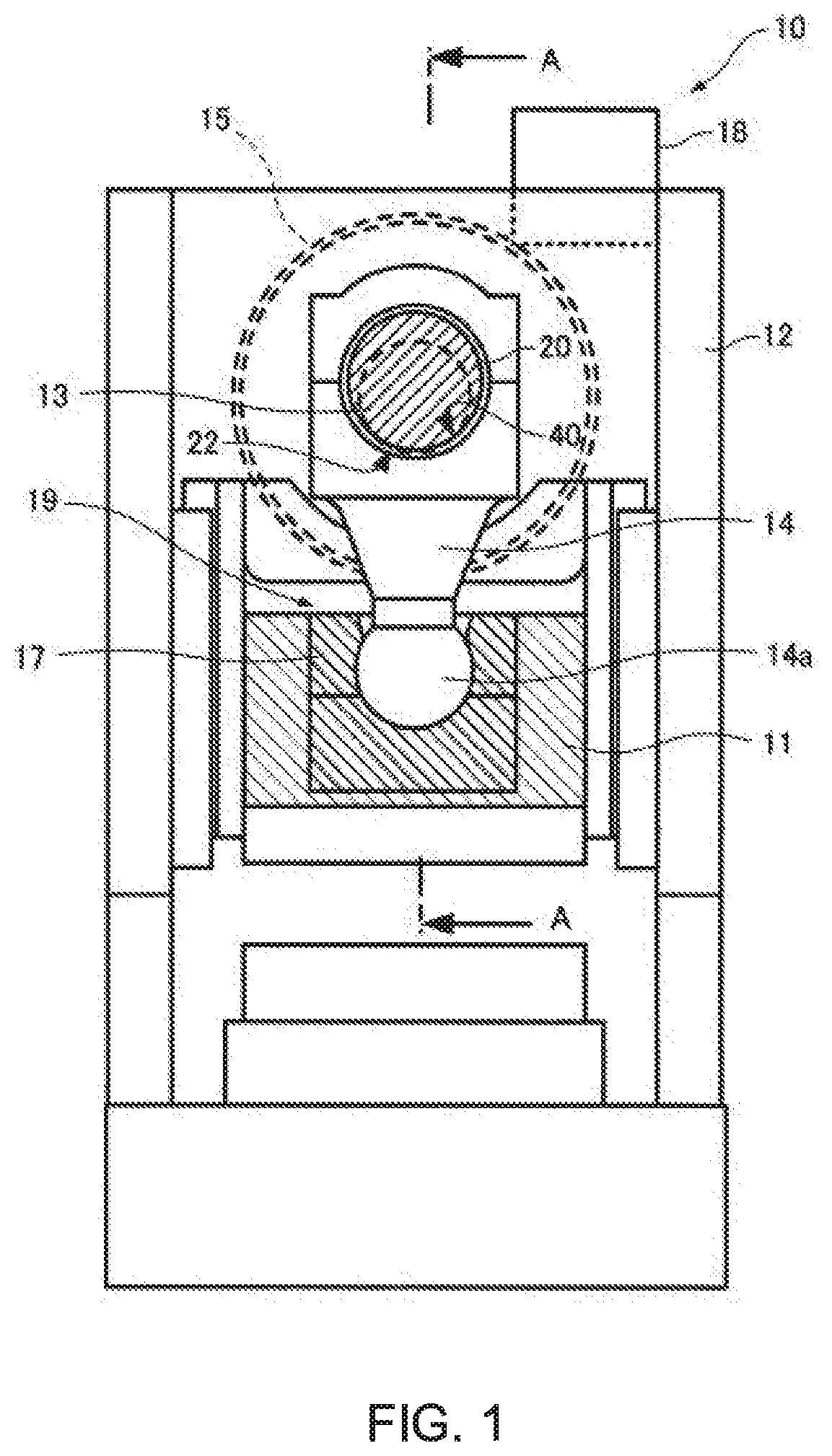
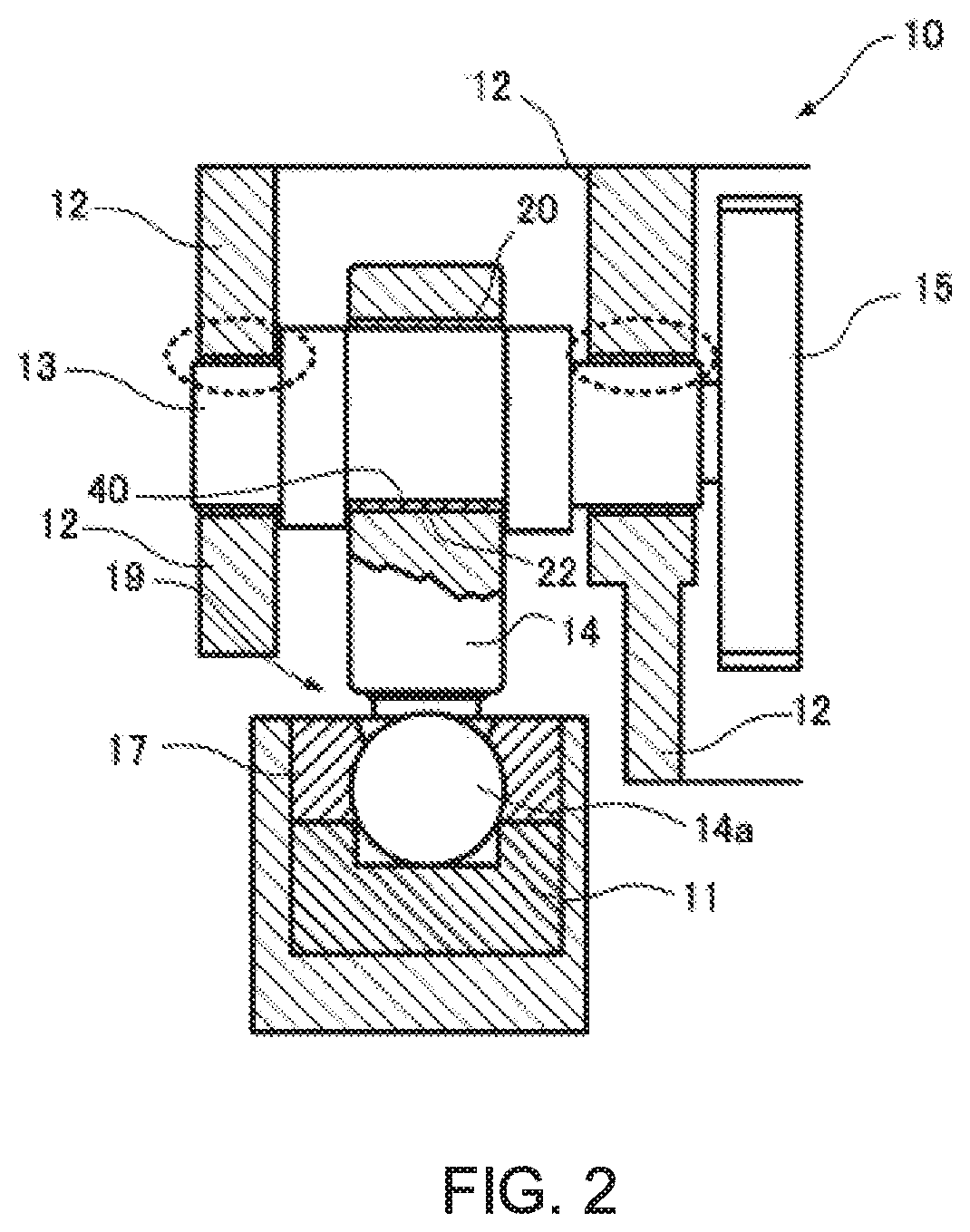
[0049]An outline of a servo press machine 10 according to the first embodiment will be described with reference to FIGS. 1 and 2. FIG. 1 is a front view of a servo press machine according to the first embodiment, and FIG. 2 is a sectional view taken along A-A in FIG. 1.

[0050]As illustrated in FIG. 1, the servo press machine 10 is provided with a frame 12, an eccentric shaft 13 rotatably supported by the frame 12, a connecting rod 14 of which a large end section is connected to the eccentric shaft 13, and a slide 11 connected to a tip section 14a of the connecting rod 14.

[0051]The servo press machine 10 is further provided with a servomotor 18 fixed to the frame 12 and a main gear 15 fixed to one end of the eccentric shaft 13. Rotational driving of the servomotor 18 can cause the main gear 15 to rotate and can rotationally drive the eccentric shaft 13. The connecting rod 14 moves upward and downward due to the rotational driving of the eccentric shaft 13, and the s...

second embodiment

3. Second Embodiment

[0079]Next, a sliding bearing 120 according to a second embodiment will be described with reference to FIGS. 8 to 10. FIG. 8 is a front view of a servo press machine 110 according to the second embodiment, FIG. 9 is an enlarged sectional view of a connecting section 119 according to the second embodiment, and FIG. 10 is a plan view of the sliding bearing 120 according to the second embodiment. The servo press machine 110 shown in FIG. 8 employs an eccentric boss as the eccentric shaft 113.

[0080]The servo press machine 110 includes: an eccentric shaft 113 that is rotationally driven by a servomotor 118; a connecting rod 114 that moves upward and downward due to the rotational driving of the eccentric shaft 113; a slide 111 that moves upward and downward as the connecting rod 114 moves upward and downward; and the connecting section 119 that connects a tip section 114a of the connecting rod 114 with the slide 111.

[0081]A rotation of the servomotor 118 is transmitte...


PUM


Abstract

A servo press machine includes an eccentric shaft, a connecting rod, a slide, an eccentric shaft-side sliding surface, a connecting rod-side sliding surface, an oil supply port, and a supply mechanism. The oil supply port opens on the eccentric shaft-side sliding surface or the connecting rod-side sliding surface, and supplies a lubricant between the eccentric shaft-side sliding surface and the connecting rod-side sliding surface. The supply mechanism supplies the lubricant to the oil supply port. The eccentric shaft-side sliding surface is formed on the eccentric shaft that is rotationally driven by a servomotor. The oil supply port is formed on the connecting rod-side sliding surface of the connecting rod that moves upward and downward due to the rotational driving of the eccentric shaft.

Description

[0001]Japanese Patent Application No. 2017-151629, filed on Aug. 4, 2017, is hereby incorporated by reference in its entirety.BACKGROUND OF THE INVENTION[0002]The present invention relates to a servo press machine and particularly to a servo press machine and a lubricant supply method that reliably supply a lubricant between two sliding surfaces.[0003]Conventionally, a sliding bearing structure is adopted between a connecting rod and a crankshaft of a press machine (for example, JP-A-2006-105371). Typically, a groove for supplying oil is provided on a bush of a sliding bearing structure provided on a connecting rod, and a lubricant is supplied to the groove in order to prevent lubrication failure of sliding portions and avoid prevent seizure in the sliding bearing structure.[0004]The groove for supplying oil provided on the bush is basically exposed to air, and the lubricant filled in the groove flows into a gap between a crankshaft and the bush and lubricates the crankshaft and the...

Claims


Application Information

Patent Timeline
Patent Type & Authority Patents(United States)
IPC IPC(8): B30B15/00B30B1/26F16N7/22F16N3/08F16C33/10F16C7/02
CPCB30B15/0088B30B1/26B30B1/266F16C7/02F16C33/1025F16C33/1045F16C33/1065F16N3/08F16N7/22
Inventor KOSHIMIZU, TAKASHI
Owner AIDA ENG LTD
Features
  • R&D
  • Intellectual Property
  • Life Sciences
  • Materials
  • Tech Scout
  • Unparalleled Data Quality
  • Higher Quality Content
  • 60% Fewer Hallucinations
Learn More