Supercharge Your Innovation With Domain-Expert AI Agents!

Hole cutter for thermoforming packaging machine and method of use

a thermoforming packaging machine and hole cutter technology, which is applied in the direction of packaging, transportation and packaging, successive articles, etc., can solve the problems of increasing the maintenance cost of the thermoforming packaging machine, increasing the operating cost of the machine, and significantly increasing the consumption of pressurized air

Active Publication Date: 2021-07-13
ULTRASOURCE
View PDF35 Cites 0 Cited by
  • Summary
  • Abstract
  • Description
  • Claims
  • Application Information

AI Technical Summary

Benefits of technology

The present invention is an apparatus and method for cutting holes and slicing through a marginal film area of a web of formed, filled and sealed product packages in a thermoforming packaging machine. The apparatus includes a rigid punch holder, film-cutting punches, a platen, and a cross cut knife. The method involves advancing the web of products between the rigid punch holder and platen, stopping the movement of the web for a short time, extending the cutting end of the punch to create a hole and a chad, and then using the cross cut knife to slice through the marginal film area. The technical effects of this invention include improved efficiency and accuracy in packaging, reduced waste and improved product quality.

Problems solved by technology

While the hole punching device described above is able to operate in a generally satisfactory manner, changing the number and positioning of the individual pneumatic cylinders can be a time-consuming process.
The use of individual pneumatic cylinders to separately punch a hole and chad in each package in a row of packages is also disadvantageous in that it increases the maintenance costs for the thermoforming packaging machine and it significantly increases the pressurized air consumption and resulting operating costs for the machine.
The threaded attachment of the cylindrical punches to the ends of the cylinder piston rods may also be problematic in that they may tend to loosen and turn over time.
This rotational turning of the punch can result in misalignment of the uncut portion of the chad or even cause the punch to extend completely through the package marginal film area and result in the chad being completely severed from the package.

Method used


Image

  • Hole cutter for thermoforming packaging machine and method of use
  • Hole cutter for thermoforming packaging machine and method of use
  • Hole cutter for thermoforming packaging machine and method of use

Examples


Embodiment Construction

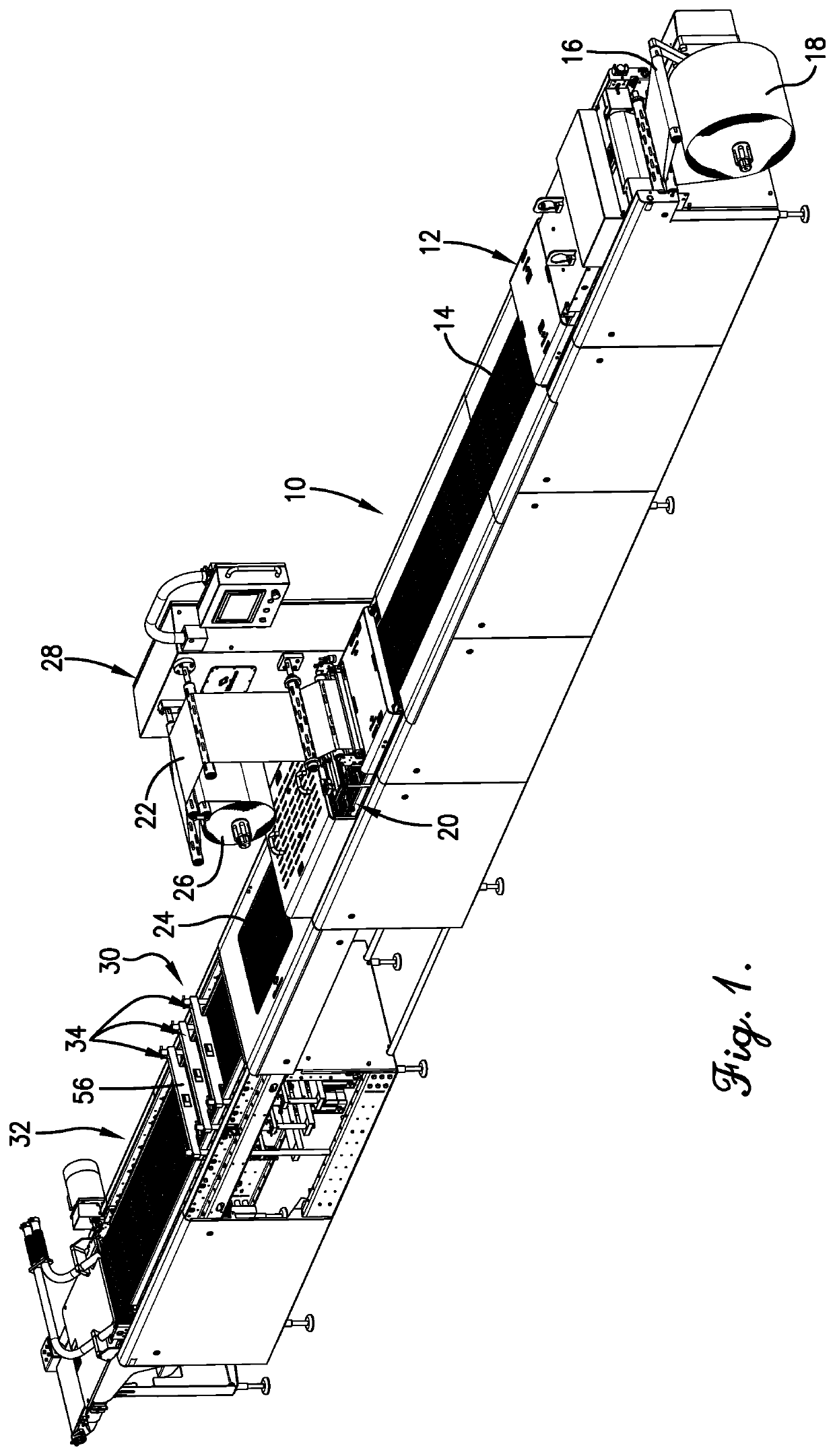
[0028]Turning now to the drawings in greater detail and initially to FIG. 1, a thermoforming packaging machine in the form of a horizontal form, fill and seal machine is designated generally by the numeral 10. The thermoforming packaging machine 10 comprising a package forming station 12 where rows of side-by-side product receptacles 14 are thermoformed in a bottom film 16 dispensed in a step-wise indexing fashion of stopped and advancing movements from a supply roll 18 mounted at one end of thermoforming packaging machine 10. A product (not shown) is placed in the web of thermoformed product receptacles 14 by hand or by using a suitable dispenser (not shown).

[0029]The thermoforming packaging machine 10 includes a sealing station 20 that heat seals or otherwise secures a top film 22 to the bottom film 16 along the peripheral margin of the product-filled, product receptacles 14 to form a number of product packages 24 that are joined together as a web. The heat seal may be but is not ...


PUM

PropertyMeasurementUnit
areaaaaaaaaaaa
longitudinal lengthaaaaaaaaaa
circumferenceaaaaaaaaaa

Abstract

An apparatus is provided for cutting holes and slicing through a web of formed, filled and sealed product packages in a thermoforming packaging machine. The apparatus uses a single actuator to move a row of film-cutting punches between extended and retracted positions for cutting holes and corresponding chads in a marginal film area of the web of thermoformed product packages and a cross cut knife to slice through the marginal film area to separate rows of the thermoformed product packages.

Description

BACKGROUND OF THE INVENTION[0001]The present invention relates generally to horizontal form, fill and seal packaging machines or other types of thermoforming packaging machines and, more particularly, to hole cutters used with such machines to punch a hole in the marginal film area of packages after they have been formed, filled and sealed in the machine so that the hole may be used to hang the packages on display rods at the point of sale. The invention also relates to methods of using the hole cutters to punch the holes in the packages.[0002]Many types of packages that are formed, filled and sealed in thermoforming packaging machines such as horizontal form, fill and seal packaging machines are intended to be hung on display rods at the point of sale. A hole is normally simultaneously punched in the top marginal film area of each package in one or more rows of packages before they are separated from each other in the thermoforming packaging machine.[0003]One device that is convent...

Claims


Application Information

Patent Timeline
Patent Type & Authority Patents(United States)
IPC IPC(8): B65B61/16B65B9/02
CPCB65B61/16B65B9/02B65B61/065
Inventor BURGESS, ERIC LEEHARTE, JAMES ROYMEISTER, DONALD FRANCIS
Owner ULTRASOURCE
Features
  • R&D
  • Intellectual Property
  • Life Sciences
  • Materials
  • Tech Scout
  • Unparalleled Data Quality
  • Higher Quality Content
  • 60% Fewer Hallucinations
Learn More