Check patentability & draft patents in minutes with Patsnap Eureka AI!

Focus adjustment method and device using a determined reliability of a detected phase difference

a phase difference and determination method technology, applied in the field of imaging devices, can solve the problems of erroneous ranging, no description regarding the use of virtual image output for positions, and inability to achieve focus, and achieve the effect of high ranging precision

Active Publication Date: 2021-09-07
OLYMPUS CORP
View PDF9 Cites 0 Cited by
  • Summary
  • Abstract
  • Description
  • Claims
  • Application Information

AI Technical Summary

Benefits of technology

[0006]The present invention provides an imaging device and a focus adjustment method of high ranging precision, when performing AF detection, even for a troublesome subject, such as a high-frequency pattern.
[0008]A focus adjustment method of a second aspect of the present invention is a focus adjustment method for an imaging device provided with an image sensor having image pixels that receive light of a subject image though a photographing lens and perform photoelectric conversion, and paired phase difference pixels that respectively receive light flux corresponding to paired pupil regions for the photographing lens and perform photoelectric conversion on the light flux that has been received, the focus adjustment method comprising detecting a phase difference based on pixel data of the paired phase difference pixels, calculating pixel data of virtual image pixels at positions of the phase difference pixels, or selecting pixel data of image pixels around positions of the phase difference pixels, calculating degree of coincidence between each pixel data of the virtual image pixels that have been calculated, or calculating degree of coincidence of each pixel data of image pixels that have been selected for positions of paired phase difference pixels, determining reliability of the phase difference detection result in accordance with the degree of coincidence, and performing focus adjustment based on the phase difference detection result and the reliability.
[0009]A non-transitory computer-readable medium of a third aspect of the present invention, storing a processor executable code, which when executed by at least one processor, the processor being provided within an imaging device provided with an image sensor having image pixels that receive light of a subject image though a photographing lens and perform photoelectric conversion, and paired phase difference pixels that respectively receive light flux corresponding to pupil regions that are paired with the photographing lens and perform photoelectric conversion on the light flux that has been received, performs a focus adjusting method, the focus adjusting method comprising detecting a phase difference based on pixel data of the paired phase difference pixels, calculating pixel data of virtual image pixels at positions of the phase difference pixels, or selecting pixel data of image pixels around positions of the phase difference pixels, calculating degree of coincidence between each pixel data of the virtual image pixels that have been calculated, or calculating degree of coincidence of each pixel data of image pixels that have been selected for positions of paired phase difference pixels, determining reliability of the phase difference detection result in accordance with the degree of coincidence, and performing focus adjustment based on the phase difference detection result and the reliability.

Problems solved by technology

This means that erroneous detection results will be adopted, and focus will be not be achieved.
However, there is no description regarding using output of virtual image pixels for positions of these phase difference pixels in AF.
In particular, in a case where arrangement positions of paired phase difference pixels of the image sensor are separated with respect to a subject of a high-frequency pattern, ranging variations occur, and there is a possibility of erroneous ranging.

Method used


Image

  • Focus adjustment method and device using a determined reliability of a detected phase difference
  • Focus adjustment method and device using a determined reliability of a detected phase difference
  • Focus adjustment method and device using a determined reliability of a detected phase difference

Examples


Embodiment Construction

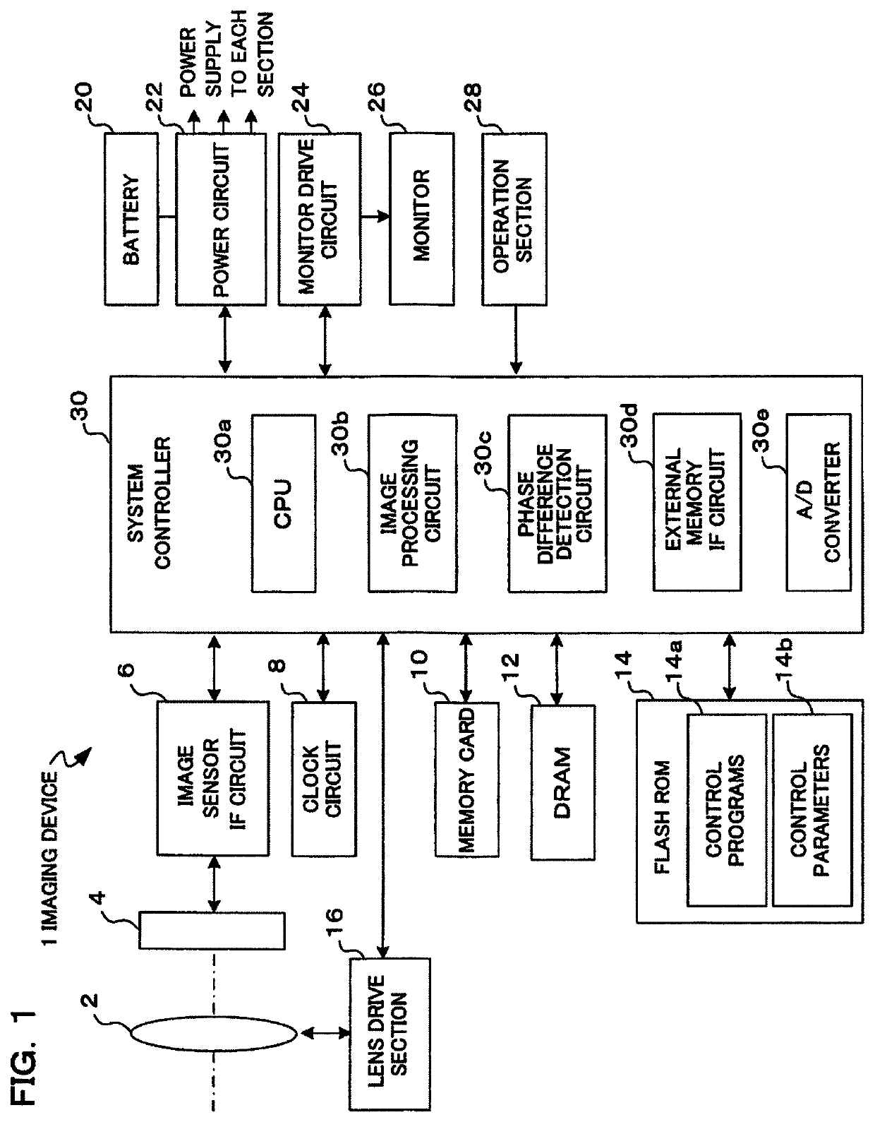
[0017]An example where the present invention has been applied to a digital camera will be described in the following as an imaging device of one embodiment of the present invention. This digital camera has an imaging section, with a subject image being converted to image data by this imaging section, and the subject image being subjected to live view display on a display section arranged on the rear surface of the camera body based on this image data that has been converted. A photographer determines composition and photo opportunity by looking at the live view display. At the time of a release operation image data is stored in a storage medium. Image data that has been stored in the storage medium can be subjected to playback display on the display section if playback mode is selected.

[0018]Also, the imaging device of this embodiment calculates virtual output of normal pixels equivalent to pixel output of image pixels corresponding to positions of pairs of phase difference pixels (...


PUM


Abstract

An imaging device, comprising an image sensor having image pixels and phase difference pixels, a phase difference detection section that detects a phase difference based on pixel data of the phase difference pixels, a pixel data calculation section that calculates pixel data of virtual imaging pixels at positions of the phase difference pixels, a degree of coincidence calculation section that calculates a degree of coincidence between each pixel data of the virtual imaging pixels that has been calculated, a reliability determination section that determines reliability of the phase difference detection result in accordance with the degree of coincidence, and a focus adjustment section that performs focus adjustment based on the phase difference detection result and the reliability.

Description

CROSS-REFERENCE TO RELATED APPLICATIONS[0001]Benefit is claimed, under 35 U.S.C. § 119, to the filing date of prior Japanese Patent Application No. 2019-047987 filed on Mar. 15, 2019. This application is expressly incorporated herein by reference. The scope of the present invention is not limited to any requirements of the specific embodiments described in the application.BACKGROUND OF THE INVENTION1. Field of the Invention[0002]The present invention relates to an imaging device that is provided with an image sensor having phase difference pixels for phase difference detection arranged on an image plane, and to a focus adjustment method of this imaging device.2. Description of the Related Art[0003]Conventionally, focus adjustment of a photographing lens has been performed using phase difference AF (Auto Focus). With phase difference AF, light flux that has passed through a pair of pupil regions of a photographing lens is subjected to photoelectric conversion by respective photoelect...

Claims


Application Information

Patent Timeline
Patent Type & Authority Patents(United States)
IPC IPC(8): H04N5/232H04N9/04
CPCH04N5/232122H04N9/0455H04N23/672H04N25/704H04N25/11
Inventor UGAWA, AKIRAKIKUCHI, TETSUO
Owner OLYMPUS CORP
Features
  • R&D
  • Intellectual Property
  • Life Sciences
  • Materials
  • Tech Scout
  • Unparalleled Data Quality
  • Higher Quality Content
  • 60% Fewer Hallucinations
Learn More