Check patentability & draft patents in minutes with Patsnap Eureka AI!

Mounting structure for mounting valve plate to valve rod in gate valve, and gate valve having mounting structure

a technology of mounting structure and valve rod, which is applied in the direction of valve arrangement, basic electric elements, electrical equipment, etc., can solve the problems of generating particles, and achieve the effect of suppressing the generation of particles due to the valve plate rubbing against the valve rod

Active Publication Date: 2021-11-16
SMC CORP
View PDF11 Cites 0 Cited by
  • Summary
  • Abstract
  • Description
  • Claims
  • Application Information

AI Technical Summary

Benefits of technology

The solution effectively suppresses particle generation by providing a firm and accurate fixation of the valve plate to the valve rod, preventing contact-induced wear and ensuring reliable operation.

Problems solved by technology

The gate valve disclosed in PTL 1, however, has a problem that the valve plate is rubbed against the valve rod or against the valve seat and particles tend to be generated when the gate valve is in operation.

Method used


Image

  • Mounting structure for mounting valve plate to valve rod in gate valve, and gate valve having mounting structure
  • Mounting structure for mounting valve plate to valve rod in gate valve, and gate valve having mounting structure
  • Mounting structure for mounting valve plate to valve rod in gate valve, and gate valve having mounting structure

Examples


Embodiment Construction

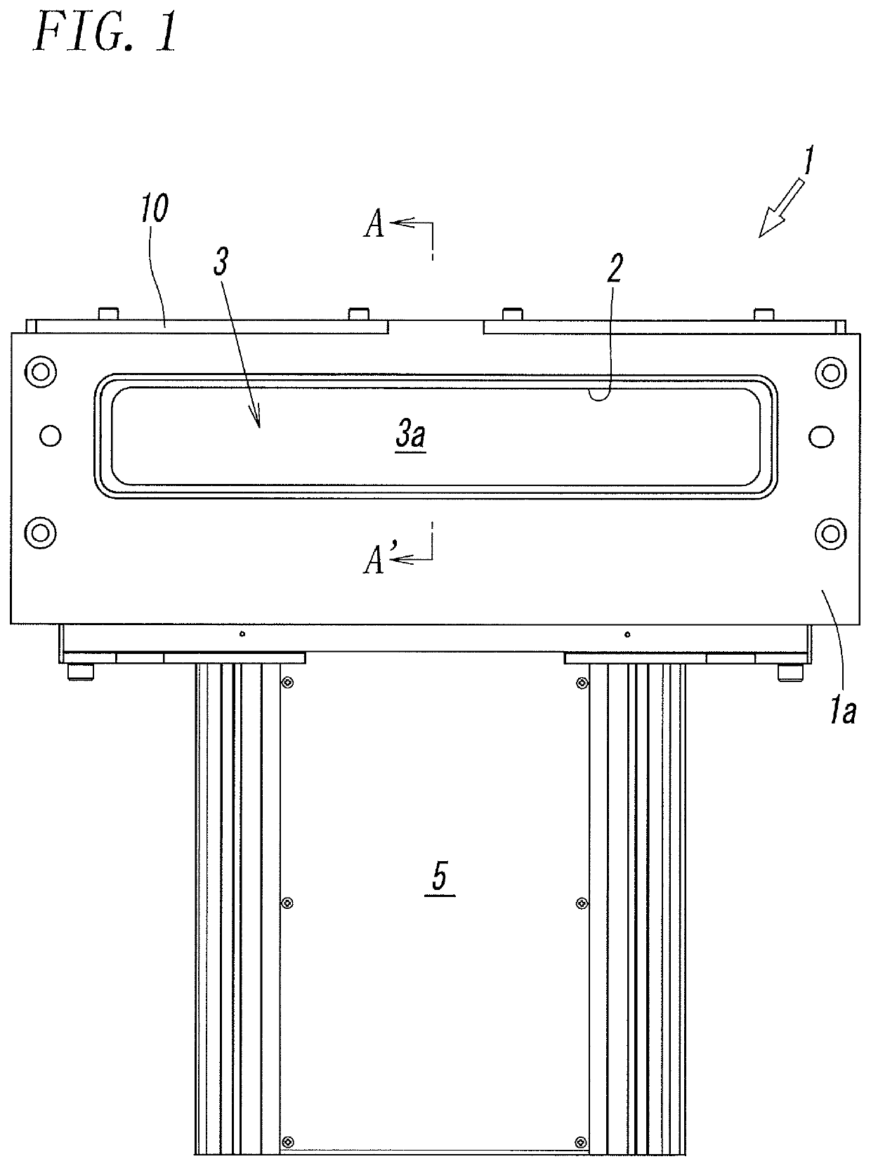
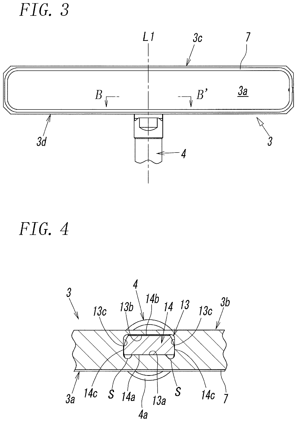
[0035]FIG. 1 and FIG. 2 illustrate an embodiment of a gate valve in which a mounting structure according to the present invention is applied to a valve rod 4 and a valve plate 3 to be mounted onto the valve rod 4. In use, the gate valve is fitted to an opening of a vacuum chamber (not illustrated). The gate valve includes a valve box 1, a valve plate 3, valve rod 4, and a valve actuator 5. The valve box 1 has a gate opening 2 to communicate with the opening of the vacuum chamber. The valve plate 3 is accommodated in the valve box 1 and configured to open and close the gate opening 2. The valve rod 4 having an axis L1 is attached to the valve plate 3 for opening and closing operation, and the valve actuator 5 moves the valve rod 4.

[0036]The gate valve is configured such that as illustrated in FIG. 2, the valve actuator 5 moves the valve rod 4 and thereby moves the valve plate 3 reciprocally between a close position, indicated by the solid line, at which the gate opening 2 is closed a...


PUM


Abstract

A spacer having a wedge-shaped flat plate portion and an engagement protrusion is interposed between a hole end surface of mounting hole of a valve plate and a rod end surface of mounting portion of a valve rod, which thereby forms a wedge-shaped gap between the spacer and the hole end surface so as to open frontward. A fastening force of a valve-plate fixation screw generates a moment M that deforms the valve plate in a direction of narrowing the gap. At the same time, the engagement protrusion of the spacer is pressed into a wedge-shaped space between the inclined surface portion of the rod end surface and the rear hole-wall surface of the mounting hole, which causes the front hole-wall surface of mounting hole of the valve plate to press the rod front surface of mounting portion of the valve rod.

Description

TECHNICAL FIELD[0001]The present invention relates to a mounting structure for mounting a valve plate onto an end of a valve rod in a gate valve and also relates to the gate valve having the mounting structure for mounting the valve plate.BACKGROUND ART[0002]A gate valve is used in a microchip processing apparatus to open and close an opening that communicates with a vacuum chamber. The gate valve is configured such that a valve plate attached to an end of the valve rod is accommodated in a valve box mounted on a vacuum chamber and the valve plate opens and closes the opening formed in a side wall of the valve box. The opening is closed by pressing a sealing member attached to the valve plate against a valve seat formed around the opening.[0003]For example, a gate valve disclosed in PTL 1 is configured such that an upper wall is detachably mounted on a valve box and a valve plate is fixed with screws to the top end of a valve rod in the axial direction thereof. This enables the valv...

Claims


Application Information

Patent Timeline
Patent Type & Authority Patents(United States)
IPC IPC(8): F16K3/18F16K51/02F16K3/02
CPCF16K3/184F16K51/02F16K3/0218F16K3/314F16K3/30F16K3/0272F16K3/16H01L21/67017
Inventor SHIMODA, HIROMIOGAWA, HIROSHINAGAO, TAKASHIOCHI, TSUYOSHI
Owner SMC CORP
Features
  • R&D
  • Intellectual Property
  • Life Sciences
  • Materials
  • Tech Scout
  • Unparalleled Data Quality
  • Higher Quality Content
  • 60% Fewer Hallucinations
Learn More