Supercharge Your Innovation With Domain-Expert AI Agents!

Jitter self-test using timestamps

a time-stamp and time-sampling technology, applied in the field of integrated circuits, can solve the problems of requiring a substantial amount of time to test each integrated circuit device, and expensive phase noise analyzers

Active Publication Date: 2022-01-18
SKYWORKS SOLUTIONS INC
View PDF8 Cites 1 Cited by
  • Summary
  • Abstract
  • Description
  • Claims
  • Application Information

AI Technical Summary

Benefits of technology

Enables fast and cost-effective jitter estimation with high resolution, reducing testing time from approximately ten seconds to 100 milliseconds and eliminating the need for expensive phase noise analyzers, while maintaining accuracy in determining RMS jitter specifications.

Problems solved by technology

Random jitter is caused by thermal noise in electrical circuits and is unpredictable, may be the composite of many uncorrelated noise sources, and typically follows a normal distribution.
Suitable phase noise analyzers are expensive and require a substantial amount of time to test each integrated circuit device (e.g., approximately ten seconds per integrated circuit device).

Method used


Image

  • Jitter self-test using timestamps
  • Jitter self-test using timestamps
  • Jitter self-test using timestamps

Examples


Embodiment Construction

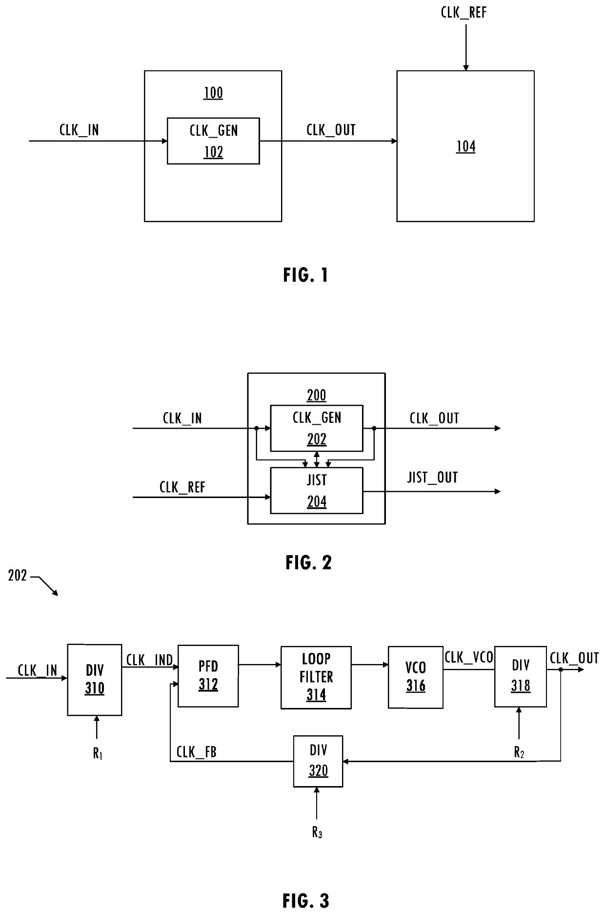
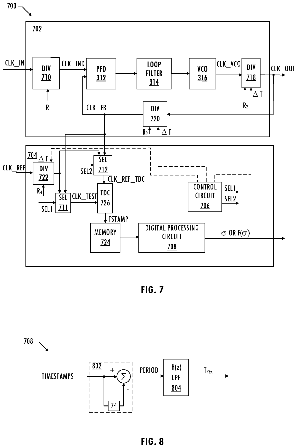
[0004]In at least one embodiment, an integrated circuit for estimating jitter of a clock signal includes a clock generator circuit configured to generate a phase-adjusted clock signal based on an input clock signal and a feedback clock signal using a frequency divider circuit. The integrated circuit includes a time-to-digital converter circuit configured to generate digital time codes corresponding to first edges of the clock signal using a reference clock signal. The integrated circuit includes a control circuit configured to cause the time-to-digital converter circuit to generate N digital time codes for each phase adjustment of P phase adjustments applied to the clock generator circuit. P is a first integer greater than zero and N is a second integer greater than zero. The integrated circuit includes a logic circuit configured to generate a jitter indicator based on an expected period of the clock signal and the N digital time codes for each phase adjustment of the P phase adjust...


PUM


Abstract

A method for estimating jitter of a clock signal includes generating a phase-adjusted clock signal based on an input clock signal and a feedback clock signal using a frequency-divided clock signal. The method generating N digital time codes for each phase adjustment of P phase adjustments of the phase-adjusted clock signal using a reference clock signal. Each digital time code of the N digital time codes corresponds to a first edge of a clock signal based on the frequency-divided clock signal. P is a first integer greater than zero and N is a second integer greater than zero. The method includes generating a jitter indicator based on an expected period of the clock signal and the N digital time codes for each phase adjustment of the P phase adjustments.

Description

BACKGROUNDField of the Invention[0001]This disclosure is related to integrated circuits and more particularly to clock generator integrated circuits.Description of the Related Art[0002]In general, jitter is unwanted deviation from true periodicity of a presumably periodic signal, e.g., a clock signal. Random jitter is caused by thermal noise in electrical circuits and is unpredictable, may be the composite of many uncorrelated noise sources, and typically follows a normal distribution. The amount of tolerable jitter varies with the target application. In an exemplary application, e.g., clock and data recovery circuits for digital communications, jitter of a sampling clock signal determines the performance of the digital communications system and as the frequency of the sampling clock signal increases, tolerance for jitter decreases. High performance phase-locked loops are used in clock generators as jitter attenuators to achieve a sampling clock signal with jitter of less than 100 f...

Claims


Application Information

Patent Timeline
Patent Type & Authority Patents(United States)
IPC IPC(8): H04L1/20G01R31/30G01R29/26G01R31/317
CPCH04L1/205G01R29/26G01R31/3016G01R31/31709G01R31/31725H04L1/24
Inventor RANGANATHAN, RAGHUNANDAN K.JAYAKUMAR, KANNANTHODATH V.SEETHAMRAJU, SRISAI R.
Owner SKYWORKS SOLUTIONS INC
Features
  • R&D
  • Intellectual Property
  • Life Sciences
  • Materials
  • Tech Scout
  • Unparalleled Data Quality
  • Higher Quality Content
  • 60% Fewer Hallucinations
Learn More