Supercharge Your Innovation With Domain-Expert AI Agents!

Aerodynamic assembly for bike handlebars

a technology for aerodynamic assembly and handlebars, which is applied in the direction of steering devices, bicycle equipment, transportation and packaging, etc., can solve the problems of not being able to adapt to a large number of cyclists, not being able to achieve a posteriori adjustment, etc., and achieve the effect of improving aerodynamics

Active Publication Date: 2022-02-01
LOOK CYCLE INT
View PDF17 Cites 0 Cited by
  • Summary
  • Abstract
  • Description
  • Claims
  • Application Information

AI Technical Summary

Benefits of technology

This solution provides improved aerodynamics and comfort by allowing precise adjustments to fit various cyclist morphologies, enhancing performance and adaptability across different riders.

Problems solved by technology

No a posteriori adjustment is consequently possible.
Such monobloc handlebars are much more ergonomic and aerodynamic than the preceding solutions, but cannot be adapted for a large number of cyclists.

Method used


Image

  • Aerodynamic assembly for bike handlebars
  • Aerodynamic assembly for bike handlebars
  • Aerodynamic assembly for bike handlebars

Examples


Embodiment Construction

[0053]In the continuation of the description, and unless disposed otherwise, elements common to all of the figures carry the same references.

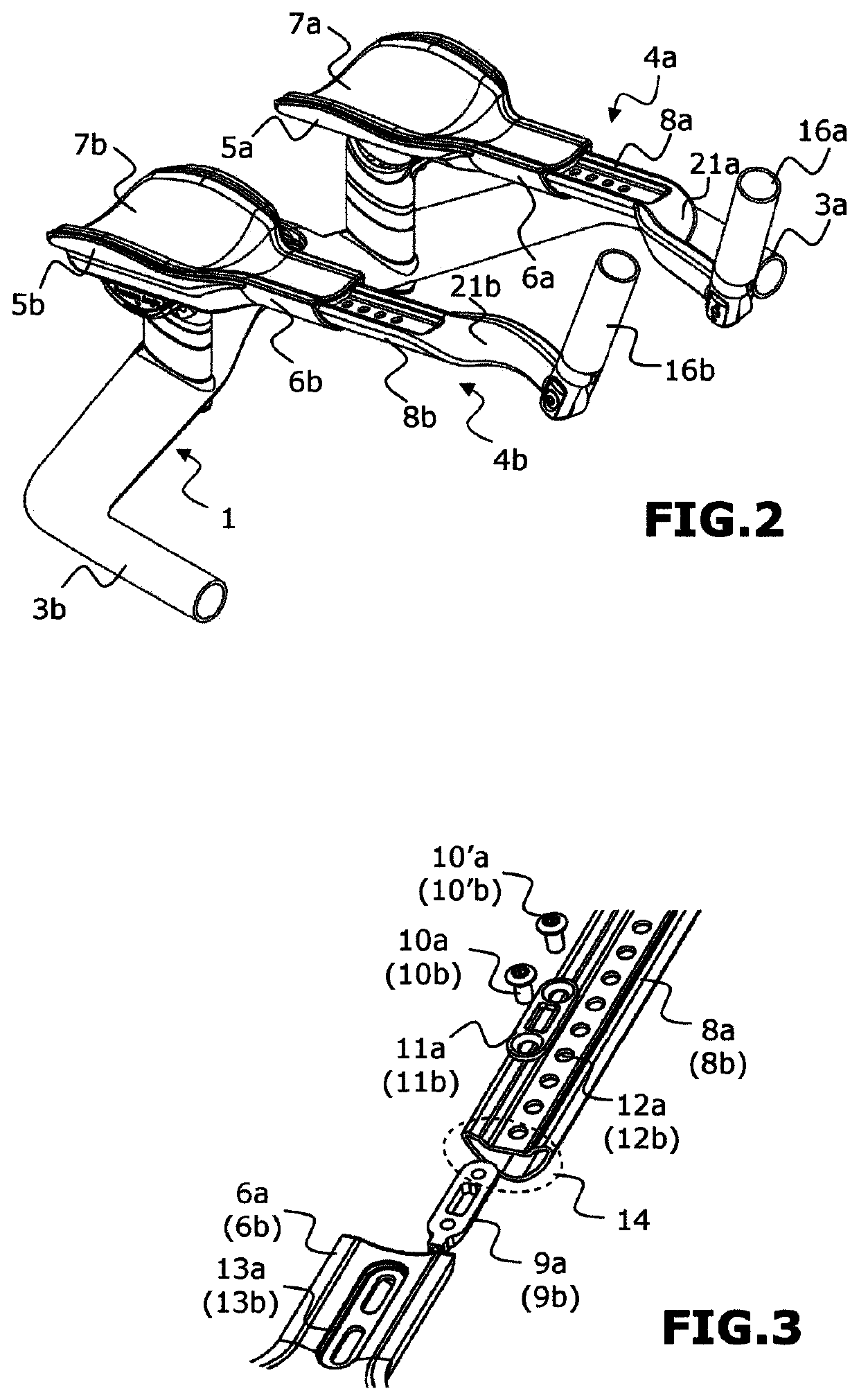
[0054]FIGS. 1 and 2 show an aerodynamic assembly for bike handlebars 1, respectively in exploded view and in assembled position. The bike handlebars 1 conventionally include a transverse bar 2, whose central part is fastened to the bike, generally by means of a stem. The transverse bar 2 is extended by a zone for taking hold or handle 3a, 3b at each of its two ends. These handles extend towards the front of the bike, substantially in the longitudinal direction of the bike, materialized on the figure by the longitudinal axis XX′. In the continuation and subject to expressly indicated exceptions, the indices “a” used in the signs of reference to the figures are representative of the parts intended to be situated on the left with respect to the longitudinal axis XX′, and the indices “b” used in the signs of reference to the figures are representat...


PUM


Abstract

An aerodynamic assembly for bike handlebars, includes two distinct extension devices (4a, 4b), each of the two extension devices (4a, 4b) having: a first armrest-forming part (5a, 5b), able to be fastened on a transverse bar of a bike handlebars (1) while extending longitudinally forwards and including a longitudinal extension (6a, 6b) forming a free end portion. An upper surface of the first part with its longitudinal extension forming a receiving surface for a forearm part of a cyclist. A second extension-forming part (8a, 8b), able to be fastened, in a removable manner and in the extension of the first part (5a, 5b), to the free end portion, the second extension-forming part (8a, 8b) being able to slide longitudinally relative to said longitudinal extension (6a, 6b) so as to allow an adjustment of a distance separating a free end of the second extension-forming part (8a, 8b) from the first armrest-forming part (5a, 5b).

Description

RELATED APPLICATION[0001]This application claims the benefit of priority from French Patent Application No. 18 53217, filed on Apr. 12, 2018, the entirety of which is incorporated by reference.BACKGROUNDField of the Invention[0002]The present invention relates in a general way to bike handlebars, for example time trial or triathlon bikes, and more precisely to the extensions that can be used for the handlebars of such bikes.Description of the Related Art[0003]Handlebars for time trial bikes allow the cyclist to have two different positions, a first position with the hands placed on the handles of the handlebars, position generally used by the cyclist when starting or for forcing, and a second position with the forearms resting on armrests and the hands placed on extensions. This second position is used by the cyclist so as to hold a cruise speed while assisting the lowering of the torso and bringing the hands and elbows of the cyclist close together, thus improving aerodynamism.[000...

Claims


Application Information

Patent Timeline
Patent Type & Authority Patents(United States)
IPC IPC(8): B62K21/12B62K21/16
CPCB62K21/125B62K21/16
Inventor BIGARD, PIERRE
Owner LOOK CYCLE INT
Features
  • R&D
  • Intellectual Property
  • Life Sciences
  • Materials
  • Tech Scout
  • Unparalleled Data Quality
  • Higher Quality Content
  • 60% Fewer Hallucinations
Learn More