Check patentability & draft patents in minutes with Patsnap Eureka AI!

Timepiece movement, timepiece, and reference position determination method of indicating hand of timepiece

a timepiece and reference position technology, applied in the direction of dynamo-electric converter control, horology, instruments, etc., can solve the problems of increasing the power consumption required for driving the timepiece, the difficulty of identifying the reference position,

Active Publication Date: 2022-06-28
SEIKO INSTR INC
View PDF9 Cites 0 Cited by
  • Summary
  • Abstract
  • Description
  • Claims
  • Application Information

AI Technical Summary

Benefits of technology

[0007]It is an aspect of the present application to provide a timepiece movement, a timepiece, and a reference position determination method of an indicating hand of a timepiece, in which means for grasping a reference position of an indicating hand can be realized using a predetermined load for enabling a normal hand operation.
[0021]According to the present application, means for grasping the reference position of the indicating hand can be realized using a predetermined load for enabling a normal hand operation.

Problems solved by technology

However, in the related art disclosed in Japanese Patent No. 3625395, if there is no load sufficient for outputting the auxiliary drive pulse in a case of detecting the non-rotation state, it is difficult to identify the reference position.
In a case of using the auxiliary drive pulse, power consumption required for driving the timepiece increases.

Method used


Image

  • Timepiece movement, timepiece, and reference position determination method of indicating hand of timepiece
  • Timepiece movement, timepiece, and reference position determination method of indicating hand of timepiece
  • Timepiece movement, timepiece, and reference position determination method of indicating hand of timepiece

Examples


Embodiment Construction

[0032]Hereinafter, an embodiment according to the present invention will be described with reference to the drawings. In the drawings used in the following description, a scale of each member is appropriately changed in order to enable each member to have a recognizable size.

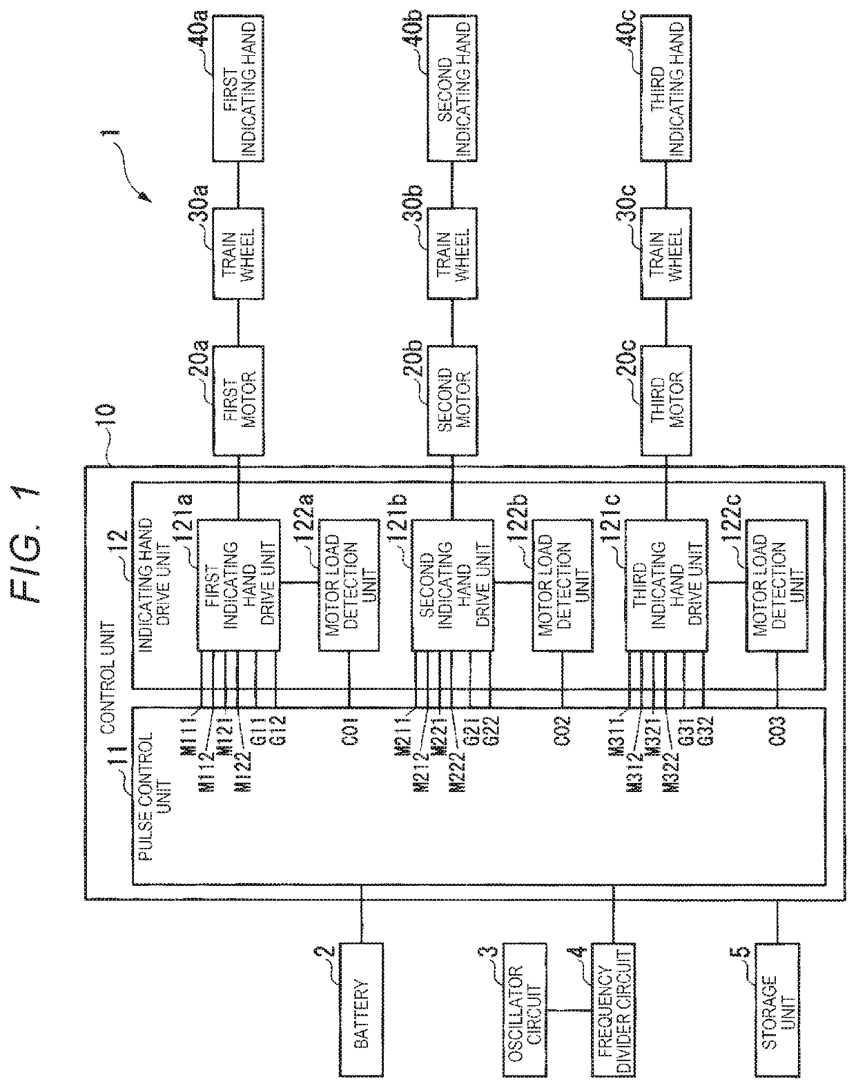
[0033]FIG. 1 is a block diagram illustrating a configuration example of a timepiece 1 according to the present embodiment. The timepiece 1 includes a battery 2, an oscillator circuit 3, a frequency divider circuit 4, a storage unit 5, a control unit 10, a first motor 20a, a second motor 20b, a third motor 20c, a train wheel 30a, a train wheel 30b, a train wheel 30c, a first indicating hand 40a, a second indicating hand 40b, and a third indicating hand 40c.

[0034]The control unit 10 includes a pulse control unit 11 and an indicating hand drive unit 12.

[0035]The indicating hand drive unit 12 includes a first indicating hand drive unit 121a, a motor load detection unit 122a, a second indicating hand drive unit 121b...


PUM


Abstract

A timepiece movement includes a stepping motor having a rotor for rotating an indicating hand, and a control unit for rotating the rotor by using a main drive pulse and an auxiliary drive pulse. When the indicating hand is rotated using a detection drive pulse based on the main drive pulse, the control unit determines a reference position of the indicating hand by detecting a rotation state of the rotor.

Description

RELATED APPLICATIONS[0001]This application claims priority under 35 U.S.C. § 119 to Japanese Patent Application Nos. 2017-203157 filed on Oct. 20, 2017 and 2018-132227 filed Jul. 12, 2018, the entire content of which are hereby incorporated by reference.BACKGROUND OF THE INVENTION1. Field of the Invention[0002]The present invention relates to a timepiece movement, a timepiece, and a reference position determination method of an indicating hand of a timepiece.2. Description of the Related Art[0003]In a timepiece, as a method of detecting a position of an indicating hand, the following method is known, for example. A hole belonging to a gear configuring a train wheel is interposed between a light emitting element and a light receiving element so as to detect the position by determining the presence or absence of transmitted light.[0004]A rotation state detection technique (for example, refer to Japanese Patent No. 5363167) has been proposed in which the indicating hand of the timepiec...

Claims


Application Information

Patent Timeline
Patent Type & Authority Patents(United States)
IPC IPC(8): G04C3/14H02P8/34H02P8/02
CPCG04C3/14G04C3/143H02P8/02H02P8/34G04C3/00
Inventor OGASAWARA, KENJI
Owner SEIKO INSTR INC
Features
  • R&D
  • Intellectual Property
  • Life Sciences
  • Materials
  • Tech Scout
  • Unparalleled Data Quality
  • Higher Quality Content
  • 60% Fewer Hallucinations
Learn More