Method and apparatus for ventilating electrical equipment on board a rail vehicle

Inactive Publication Date: 2001-12-13
ALSTOM SA
View PDF0 Cites 4 Cited by
  • Summary
  • Abstract
  • Description
  • Claims
  • Application Information

AI Technical Summary

Benefits of technology

0003] The object of the present invention is thus to propose a method and apparatus for ventilating electrical equipment on board a rail

Problems solved by technology

However, such ventilation apparatus has the drawback of causing the various fans to operate collectively.
Thus, as soon as any one of the fans is required to operate at full power in order to ensure that the electrical

Method used


Image

  • Method and apparatus for ventilating electrical equipment on board a rail vehicle

Examples


Embodiment Construction

[0014] To make the drawing easier to understand, only the elements necessary for understanding the invention are shown.

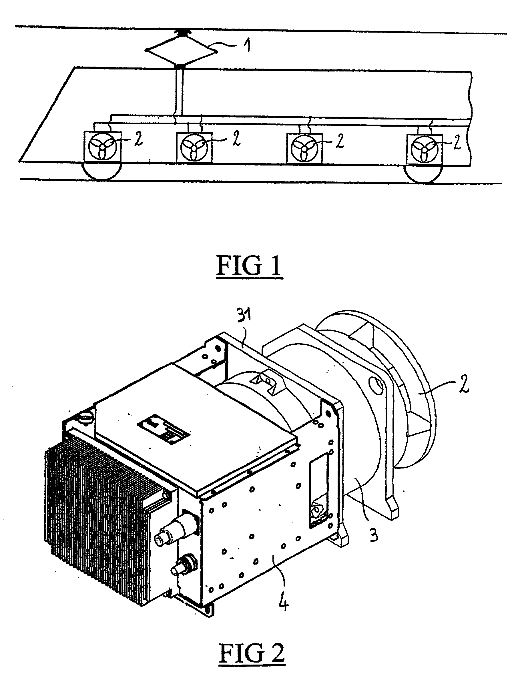
[0015] FIG. 1 shows a rail vehicle power car that is electrically powered by means of a pantograph device 1 connected to a catenary supplying 750V DC.

[0016] In FIG. 1, the carriage is fitted with electrical equipment of the traction motor, transformer, electronic power unit, and braking rheostat type, each piece of equipment including a respective cooling fan 2 driven by an asynchronous electric motor 3.

[0017] In FIG. 2, a DC / AC converter 4 is integrated on the stand of each asynchronous motor 3 so as to transform the 750V DC from the catenary into three-phase AC powering the asynchronous motor 3. The converter 4 is fixed by screws onto a collar 31 of the stand of the electric motor 3, thus providing a compact assembly, comprising a converter 4, a motor 3, and a fan 2.

[0018] The converter 4 is made up of IGBTs and delivers a modulatable output frequency f, at a cons...


PUM


Abstract

Apparatus for ventilating electrical equipment on board a rail vehicle, said rail vehicle being powered with DC either directly by an electricity pick-up system connected to a DC source, or indirectly by rectifying and filtering electricity picked up by an electricity pick-up system connected to a single-phase AC source, each piece of electrical equipment being ventilated by means of a respective cooling fan controlled by an electric motor, wherein the electric motors are asynchronous motors, each fan electric motor being powered with three-phase AC by an individual converter connected to the DC for powering the rail vehicle.

Description

[0001] The invention relates to a method and apparatus for ventilating electrical equipment on board a DC-powered rail vehicle, and more particularly to ventilation apparatus including, for each piece of electrical equipment, an associated fan controlled by an electric motor. The ventilation apparatus preferably applies to rail traction vehicles, such vehicles having many pieces of ventilated electrical equipment on board.[0002] Normally, each piece of power equipment in a power car, such as transformers, traction motors, braking rheostats, and electronic power units, are individually cooled, each by means of a respective fan driven by an electric motor, all of the motors being powered with electricity by the same converter, on board the car, that transforms the DC available at the catenary into AC suitable for operating power equipment. However, such ventilation apparatus has the drawback of causing the various fans to operate collectively. Thus, as soon as any one of the fans is r...

Claims


Application Information

Patent Timeline
IPC IPC(8): B60K11/06B61C17/00B61C17/04B61D27/00H02K7/14H02K9/04H02K17/00H05K7/20
CPCB61C17/04H02K7/14H02K9/04Y02T10/641Y02T30/10B60L2200/26H02K17/00Y02T10/64Y02T30/00B61C17/00H05K7/20172H02M7/42F04D25/08F04D25/06
Inventor MARY, BERNARDLIEVREMONT, GILLES
Owner ALSTOM SA
Why Eureka
Try Eureka