Supercharge Your Innovation With Domain-Expert AI Agents!

Failure diagnosis apparatus for exhaust gas recirculation system

a technology of failure diagnosis and exhaust gas, which is applied in the direction of apparatus for force/torque/work measurement, electrical control, instruments, etc., can solve the problems of measurement error of air-flow meter, different estimated pressure, and limitation of accuracy in correcting estimated pressur

Inactive Publication Date: 2003-06-12
HITACHI LTD +1
View PDF1 Cites 32 Cited by
  • Summary
  • Abstract
  • Description
  • Claims
  • Application Information

AI Technical Summary

Problems solved by technology

However, there are various factors that cause an error in an estimated suction pipe pressure in practice, including dispersion of suction / exhaust temperature, dispersion of post-exhaust-stroke cylinder residual gas pressure, dispersion of actual throttle valve opening area, and error in air-flow meter, and consequently influence on the estimated pressure is different.
Besides, the influence of a measurement error of the air-flow meter appears as an error on an intake air flow dependent portion 2807 of the estimated suction pipe pressure.
For the above reasons, there has been a limitation of accuracy in correcting the estimated pressure simply by adjusting the estimated pressure with gains as in the above-mentioned known art.
There has been another problem that, if the EGR gas temperature is lower than expected like in a case that the exhaust gas recirculation system has not yet been warmed up sufficiently and therefore heat of the EGR gas is absorbed by the exhaust gas recirculation system, the EGR flow may be wrongly judged lower and faulty because the actual pressure of the EGR gas becomes lower even if the EGR mass flow is normal.
There has been another problem that, since the purge valve mounted on the suction pipe is operated under a duty control, pulses are caused in the suction pipe pressure by the incoming gas through the valve and the accuracy of diagnosis is badly affected.
There remains a further problem that, if purging is stopped during the diagnosis so as to prevent the above, the purge gas discharge increases.
Because of this, the EGR pressure calculated from the measured suction pipe pressure and estimated fresh air pressure results in a smaller value, and consequently there remains a possibility that the EGR flow is wrongly judged lower and faulty.
Delay of the estimated fresh air pressure is of another problem.
This error causes a problem that, even if the estimated fresh air pressure is corrected by an internal combustion engine parameter modifying means 2705, the estimated value shifts as the operating condition varies.

Method used


Image

  • Failure diagnosis apparatus for exhaust gas recirculation system
  • Failure diagnosis apparatus for exhaust gas recirculation system
  • Failure diagnosis apparatus for exhaust gas recirculation system

Examples


Embodiment Construction

:

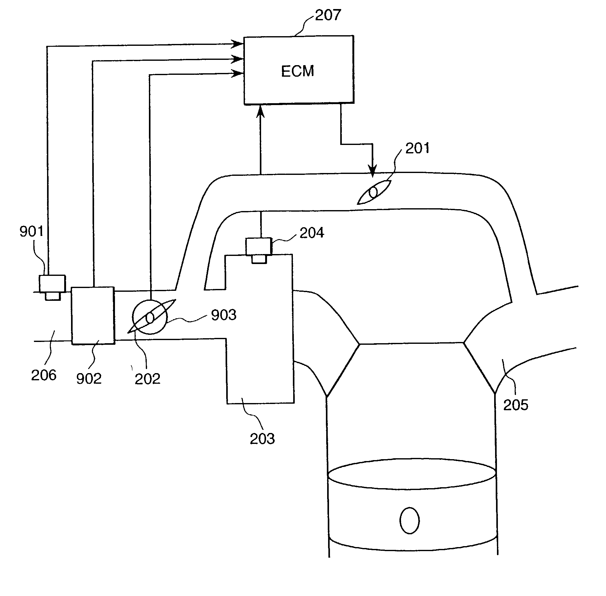
[0083] A preferred embodiment of a failure diagnosis apparatus for an exhaust gas recirculation system of the present invention is explained hereunder, using figures.

[0084] FIG. 18 shows an overall structure of an internal combustion engine system equipped with a preferred embodiment of a failure diagnosis apparatus for an exhaust gas recirculation system of the present invention. The system consists of an internal combustion engine, suction system, and exhaust system. The internal combustion engine is equipped with an igniter 109, fuel injection system 119, and speed detecting means 113. The suction system is equipped with an air cleaner, suction air temperature detecting means 104, air flow detecting means 103, and suction pipe pressure detecting means 107. The exhaust system is equipped with an air / fuel ratio sensor 111 and catalytic converter rhodium.

[0085] An internal combustion engine controlling unit 115 finds a ring gear or plate speed Ne from an output signal Qa of the air...


PUM


Abstract

To provide a failure diagnosis apparatus for an exhaust gas recirculation system which is capable of eliminating the influence of various disturbance factors that vary the suction air pressure, diagnosing a failure of the exhaust gas recirculation system on the basis of the suction air pressure, and preventing wrong diagnosis. A failure diagnosis apparatus for an exhaust gas recirculation system consists of a fresh air pressure estimating means 2911 for calculating an estimated fresh air pressure inside a suction pipe from the operating condition of an internal combustion engine, an actual EGR (exhaust gas recirculation) gas pressure estimating means 2914 for estimating an EGR gas pressure on the basis of a measured suction pipe pressure detected by a suction pipe pressure detecting means 2911 and an estimated fresh air pressure calculated above, and a failure judging means 2910 for judging the failure on the basis of the estimated EGR gas pressure and the detected operating condition.

Description

BACKGROUND OF THE INVNETION[0001] 1. Technical Field[0002] The present invention relates to a failure diagnosis apparatus for an exhaust gas recirculation system of an internal combustion engine.[0003] 2. Prior Art[0004] An art disclosed in Japanese Patent Application Laid-Open Publication No. HEI 10-115259 (1998) represents a conventional failure diagnosis apparatus of this type for an exhaust gas recirculation system. FIG. 16 is a block diagram of the functional configuration of a conventional failure diagnosis apparatus for an exhaust gas recirculation system.[0005] Shown in the figure are an EGR valve controlling means 2703, an internal combustion engine condition parameter detecting means 2702, an internal combustion engine condition parameter estimating means 2701, an internal combustion engine condition parameter comparing means 2704 for comparing the detected and estimated internal combustion engine parameters, an EGR flow judging means 2706 for diagnosing an EGR flow on the...

Claims


Application Information

Patent Timeline
Patent Type & Authority Applications(United States)
IPC IPC(8): F02D21/08F02D41/00F02D41/22F02D45/00F02M25/07
CPCF02D21/08F02D41/0055F02D41/0072F02D41/221Y02T10/47F02D2200/0406F02D2200/0408F02M25/0702F02M25/0715F02D2200/0402F02M26/49F02M26/13Y02T10/40
Inventor OSAKI, SATORUHORI, TOSHIOMATSUNO, OSAMUTSUYUKI, TAKESHI
Owner HITACHI LTD
Features
  • R&D
  • Intellectual Property
  • Life Sciences
  • Materials
  • Tech Scout
  • Unparalleled Data Quality
  • Higher Quality Content
  • 60% Fewer Hallucinations
Learn More