Check patentability & draft patents in minutes with Patsnap Eureka AI!

Tire sensor insertion tool and method

a technology for insertion tools and sensors, which is applied in the direction of vehicle tyre testing, instruments, roads, etc., can solve the problems of difficult insertion of sensors, thermocouples or other relatively fragile electronic devices into rubber, impede the progress of devices, damage to devices, etc., and achieve the effect of convenient replacement machined

Inactive Publication Date: 2005-02-17
THE GOODYEAR TIRE & RUBBER CO
View PDF14 Cites 3 Cited by
  • Summary
  • Abstract
  • Description
  • Claims
  • Application Information

AI Technical Summary

Benefits of technology

The invention is a tool and method for inserting a sensor to a specific depth within a bore. The tool has a tip with a sensor attached, which is pulled through the handle until it reaches the tip. The tip is then inserted into the bore and removed, leaving the sensor in place. The tool can also be used to insert a thermocouple, with a window allowing for visual tracking of its progress. The tool tip is designed for easy replacement and the handle provides mechanical advantage for insertion and withdrawal. The technical effects of the invention include improved accuracy and efficiency in sensor insertion and the ability to easily replace the tool tip for different depths.

Problems solved by technology

It is, however, very difficult to insert a sensor, thermocouple, or other relatively fragile electronic device into rubber due to inherent properties of rubber that complicate such an insertion.
Contact between the rubber tire and a device inserted therein may result in damage to the device or impede the progress of the device into the tire bore to an extent that prohibits the device from reaching its optimum depth.
Moreover, it is difficult to determine when the device has reached its intended depth.
Continued application of insertion force against the sensor after it reaches the terminal end of the bore can also result in sensor damage and consequent malfunction.

Method used


Image

  • Tire sensor insertion tool and method
  • Tire sensor insertion tool and method
  • Tire sensor insertion tool and method

Examples


Embodiment Construction

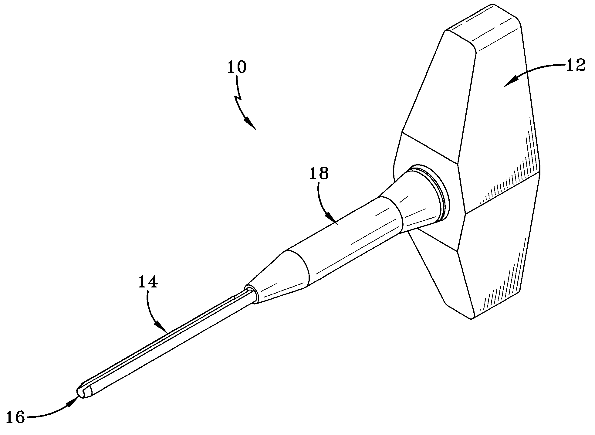
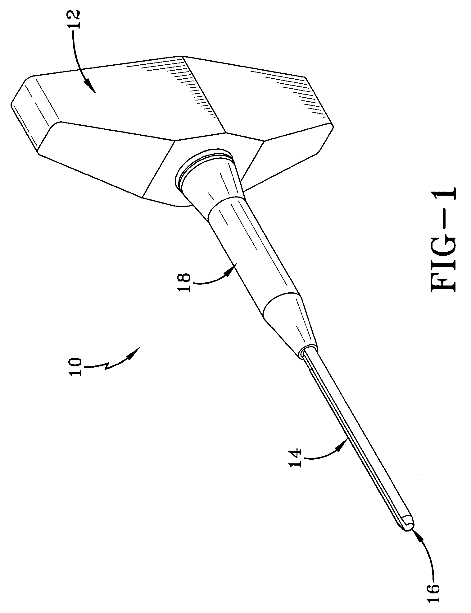
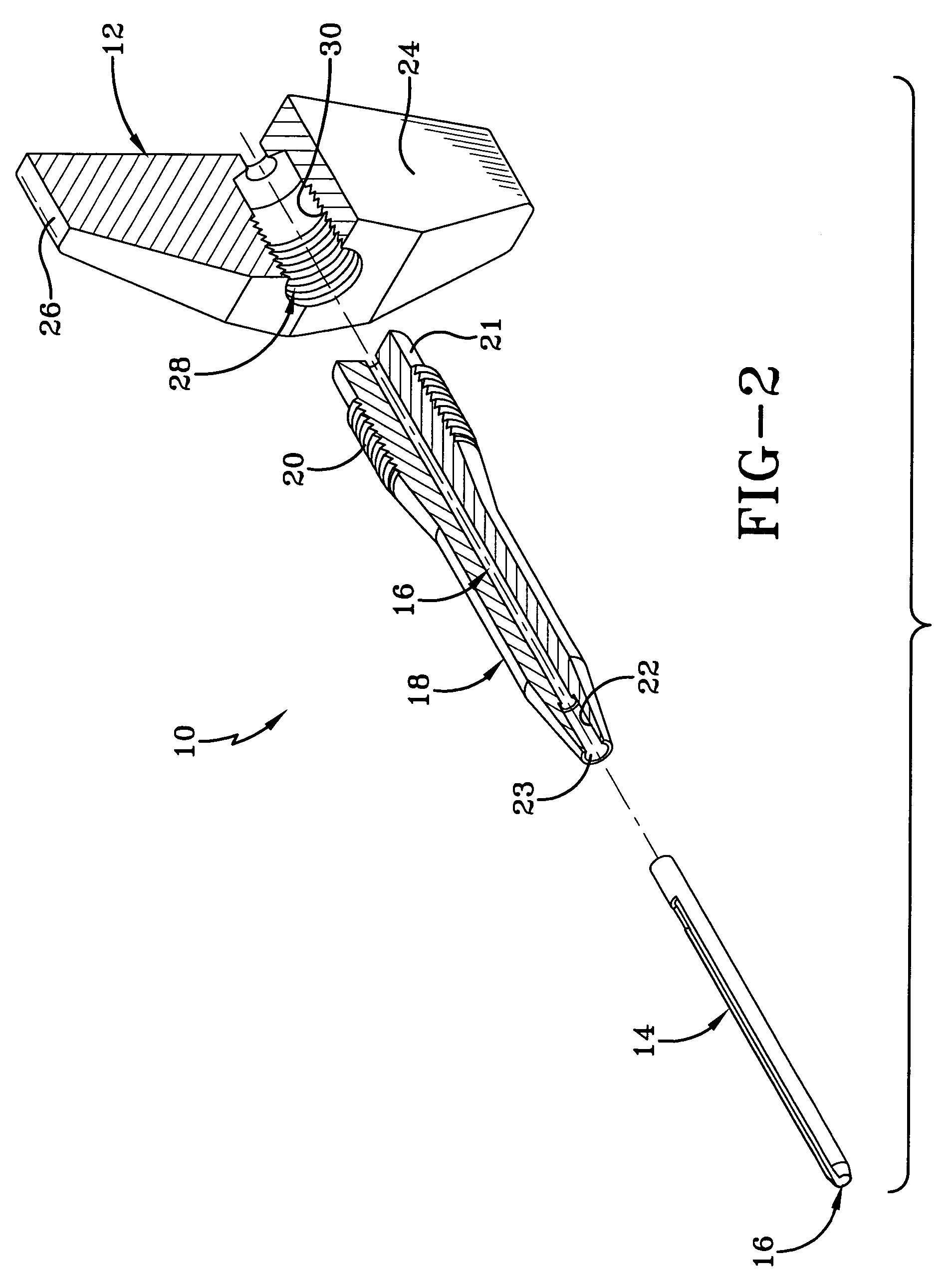
[0018] Referring initially to FIGS. 1, 2, and 3, the subject insertion tool 10 is shown to comprise a generally T-shaped handle 12 and an elongate tool tip 14. The handle 12 and tip 14 may be preferably formed from any suitable material such as steel. An axial passageway 16 extends through the handle 12 and the tip 14. The handle 12 comprises an elongate nose member 18 having circumferential screw threads 20 formed proximate a rearward end 21 and a socket 22 formed to extend into a forward end 23. A gripping portion of the handle 12 includes opposite wing grip flanges 24, 26. A socket 28 extends between the grip flanges 24, 26 coaxial with passageway 16. The socket 28 includes internal circumferential threads 30.

[0019] The tip member 14 is preferably formed as a machined roll pin extending between a forward tip end 32 and a rearward tip end 34. The pin body 36 is elongate and cylindrical and formed to provide an elongate slit 38 extending therein to the passageway 16. An enlarged p...


PUM


Abstract

A tool for insertion of a sensor to a predetermined depth within a bore includes an elongate tool tip terminating at a tip end, a handle affixed to the tip, and an axial passageway extending through the tip and handle to a tool end. A window is provided extending transversely into the tool tip at a location between the tip end and the handle and provides visual access to the passageway. The tool is capable of use in two modes of operation. In a first mode, a bore is drilled into an object body such as a tire to the required depth. The sensor leads are fed through the tip of the tool and pulled through the handle until the sensor touches the tip of the tool. Thereafter, the tip of the tool with the sensor is inserted into the pre-formed bore. The tool tip is then removed out of the bore, leaving the sensor within the bore at the pre-determined desired depth. In the second mode of operation, the tip of the tool is inserted into the pre-drilled bore and a thermocouple is inserted into the bore via the axial passageway extended through the tool tip and handle. The progress of the thermocouple insertion is tracked through the window. A marking or other indicia may be placed on the trailing leads of the thermocouple at a predetermined spacing from the thermocouple. Visual identification of the arrival of the indicia at the tool tip window indicates a successful insertion of the thermocouple to its intended depth. Thereafter the tool tip is removed, leaving the thermocouple within the bore at the predetermined, optimal depth.

Description

FIELD OF THE INVENTION [0001] The invention relates generally to a tool for positioning a sensor within an elongate bore and, more specifically, to a tool and method for inserting a tire sensor or other electronic measuring device to a predetermined depth within a tire bore. BACKGROUND OF THE INVENTION [0002] It is desirable to monitor physical properties of a tire during test procedures in order to ascertain and measure certain tire performance characteristics such as temperature. Certain tests involve taking temperature measurements of a tire tread by imbedding a temperature sensor or thermocouple into the tread region of the tire. To conduct such tests, a bore is drilled into the tread region and the sensor or thermocouple is inserted into the bore. It is, however, very difficult to insert a sensor, thermocouple, or other relatively fragile electronic device into rubber due to inherent properties of rubber that complicate such an insertion. Contact between the rubber tire and a d...

Claims


Application Information

Patent Timeline
Patent Type & Authority Applications(United States)
IPC IPC(8): B25B27/04
CPCB25B27/04
Inventor FENKANYN, JOHN MICHAEL
Owner THE GOODYEAR TIRE & RUBBER CO
Features
  • R&D
  • Intellectual Property
  • Life Sciences
  • Materials
  • Tech Scout
  • Unparalleled Data Quality
  • Higher Quality Content
  • 60% Fewer Hallucinations
Learn More