Calender for a sheet of paper
a technology of calender and paper, which is applied in the field of calender for paper, can solve the problems of sleeve b>2/b> being easily slipped, gaps being produced, and deformation of the sleev
- Summary
- Abstract
- Description
- Claims
- Application Information
AI Technical Summary
Benefits of technology
Problems solved by technology
Method used
Image

Examples
first embodiment
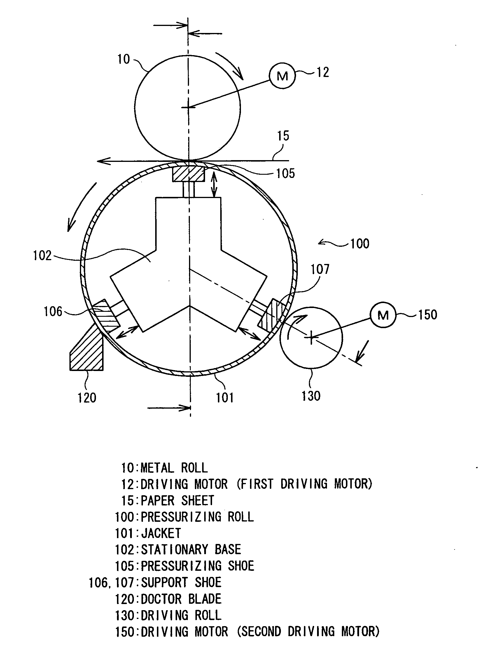
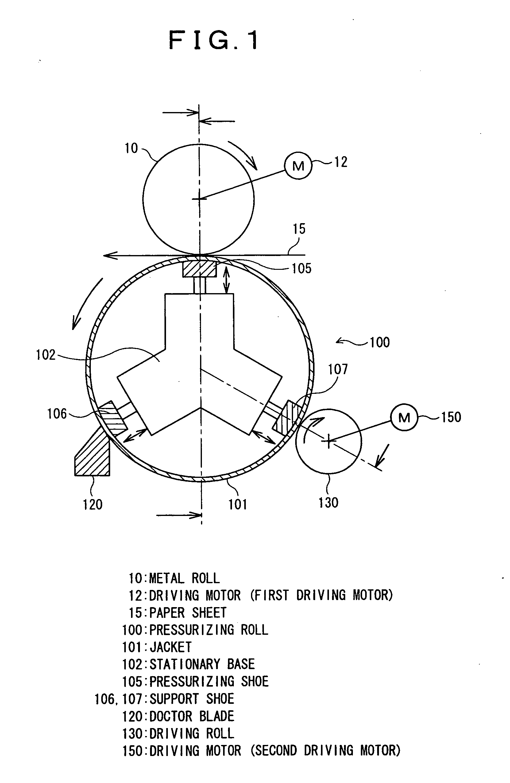
[0083] In the above-described first embodiment, even when the jacket 101 is protruded by the pressuring shoe 105 pressurized for a calendering process, the support shoes 106, 107 protrude outward in the radial direction of the jacket 101 at the same time so that the circular shape of the jacket 101 is held.
[0084] In addition, even if the jacket 101 bulges due to deformation caused by applied pressure and rotation, the driving roll 130 and doctor blade 120 act on the outer periphery of the jacket 101 to prevent deformation. As a result, the jacket 101 can be held in a state near to a circle.
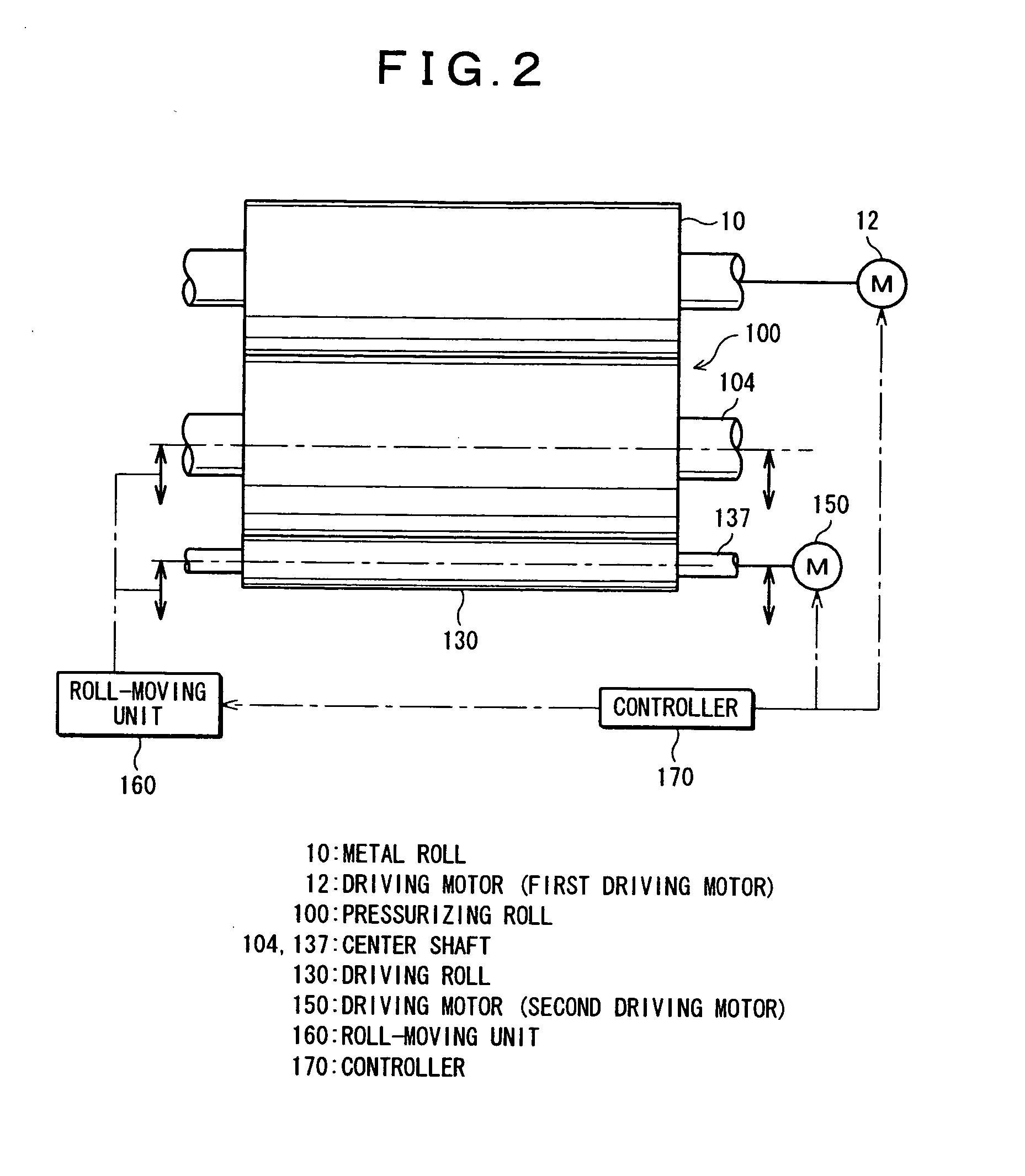
[0085] As shown in FIG. 2, the calender of the first embodiment is equipped with a driving motor (second driving motor) 150 which drives the driving roll 130 that rotates the jacket 100, and a roll-moving unit 160 which moves the jacket 101 between a first position where the jacket 101 is pressed against the metal roll 10 and a second position where the jacket 101 is moved away from the metal rol...
second embodiment
[0100] Now, the present invention will be described with reference to FIG. 4.
[0101]FIG. 4 shows the driving roll of a calender constructed in accordance with the second embodiment of the present invention. In the second embodiment, the driving roll 130 in the above-described first embodiment is replaced with a divided type. Since the remaining construction is the same as the first embodiment, a description will be given of different parts. Note in FIG. 4 that the same parts as FIG. 2 are represented by the same reference numerals.
[0102] A driving roll 130 in the second embodiment is constructed of a plurality of rolls 135 divided in the axial direction of a pressurizing roll 100. The rolls 135 are rotated by a driving motor 150 through a connecting shaft 136. The weight of the rolls 135 of the second embodiment is reduced, compared with the driving roll 130 of the first embodiment. As a result, power of the driving motor 150 can be saved. In addition, since the jacket 101 is suppor...
third embodiment
[0103] Now, the present invention will be described with reference to FIG. 5.
[0104]FIG. 5 shows the doctor blade of a calender constructed in accordance with the third embodiment of the present invention. In the third embodiment, the doctor blade 120 in the above-described first embodiment is replaced with a divided type. Since the remaining construction is the same as the first embodiment, a description will be given of different parts. Note in FIG. 5 that the same parts as FIG. 3 are represented by the same reference numerals.
[0105] A doctor blade 120 in the third embodiment is constructed of two doctor blades divided in the axial direction of a pressurizing roll 100. The two doctor blades 125 are disposed on a support plate 126 with a space. The doctor blades 125 are slid a predetermined quantity in the axial direction of the pressurizing roll 100 by a driving unit M so that paper dust, etc., are removed over the entire surface of the jacket 101 of the pressurizing roll 100.
[01...
PUM
| Property | Measurement | Unit |
|---|---|---|
| speed | aaaaa | aaaaa |
| driving torque | aaaaa | aaaaa |
| pressurizing force | aaaaa | aaaaa |
Abstract
Description
Claims
Application Information
 - R&D
- Intellectual Property
- Life Sciences
- Materials
- Tech Scout
- Unparalleled Data Quality
- Higher Quality Content
- 60% Fewer Hallucinations
Browse by: Latest US Patents, China's latest patents, Technical Efficacy Thesaurus, Application Domain, Technology Topic, Popular Technical Reports.
© 2025 PatSnap. All rights reserved.Legal|Privacy policy|Modern Slavery Act Transparency Statement|Sitemap|About US| Contact US: help@patsnap.com