Supercharge Your Innovation With Domain-Expert AI Agents!

Axial magnetic bearing apparatus

a technology of axial magnetic bearings and axial magnetic bearings, which is applied in the direction of bearing cooling, mechanical equipment, mechanical energy handling, etc., can solve the problems of increasing rotor mass, difficult to apply the above-mentioned background-art improved axial magnetic bearing apparatus to the mechanism supporting a high-speed rotating body, etc., to achieve effective utilization, increase radial magneto-resistance, and improve control performance

Inactive Publication Date: 2005-05-12
MITSUBISHI ELECTRIC CORP
View PDF7 Cites 4 Cited by
  • Summary
  • Abstract
  • Description
  • Claims
  • Application Information

AI Technical Summary

Benefits of technology

[0022] Then, according to these configurations, magnetic interference between two magnetic circuits formed by the respective electromagnetic stators is relieved. As a result, it is possible to relieve the formation of an abnormal magnetic circuit extending from one electromagnetic stator to the other electromagnetic stator through the rotary disc and extending from the other electromagnetic stator to the one electromagnetic stator through the rotor disc. Thus, electric energy supplied to the electromagnetic coils is effectively utilized to control the position of the rotating shaft so that it is possible to improve the control performance. In addition, the rotary disc is integrally coupled in the portion where no deep groove or no through hole is provided. Thus, even if maximum stress is generated due to centrifugal force at the time of high speed rotation in the rotation-axis-direction position of the inner diameter of the rotary disc having a maximum outer diameter, the stress is relieved so that the fixation between the rotating shaft and the rotary disc is retained surely.
[0029] Further, according to the present invention, a collar made of a non-magnetic material for relatively positioning where the pair of electromagnetic stators are attached is provided between the pair of electromagnetic stators. Accordingly, two magnetic circuits formed by the respective electromagnetic stators are insulated from each other magnetically. As a result, it is possible to more surely prevent the formation of an abnormal magnetic circuit extending from one electromagnetic stator to the other electromagnetic stator through the collar and extending from the other electromagnetic stator to the one electromagnetic stator through the rotor disc. Thus, electric energy supplied to the electromagnetic coils is effectively utilized to control the position of the rotating shaft so that it is possible to improve the control performance.

Problems solved by technology

It is difficult to realize such a support mechanism by a mechanical contact type bearing.
Thus, there arises a problem that the fixation between the rotating shaft 1 and the rotary disc 2 is retained only at a part of the sleeves 6.
Thus, there has been also a problem that such a structure is disadvantageous because the number of parts is increased, and the rotor mass is also increased.
That is, there has been a problem that it is difficult to apply the above-mentioned background-art improved axial magnetic bearing apparatus to a mechanism for supporting a high-speed rotating body.

Method used


Image

  • Axial magnetic bearing apparatus
  • Axial magnetic bearing apparatus
  • Axial magnetic bearing apparatus

Examples


Embodiment Construction

[0042] Modes for carrying out the present invention will be described below in detail with reference to FIGS. 1 to 7.

Mode 1.

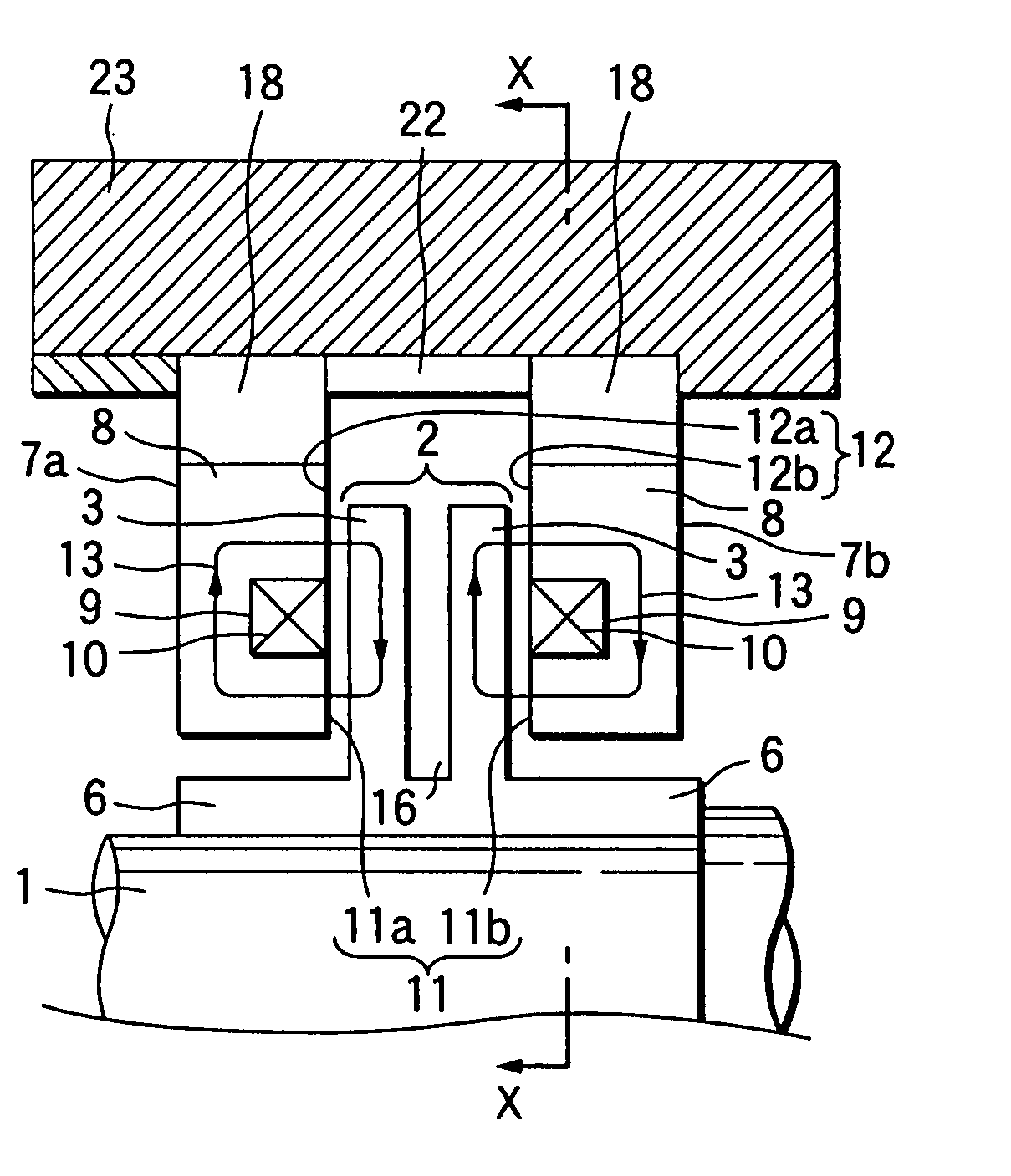
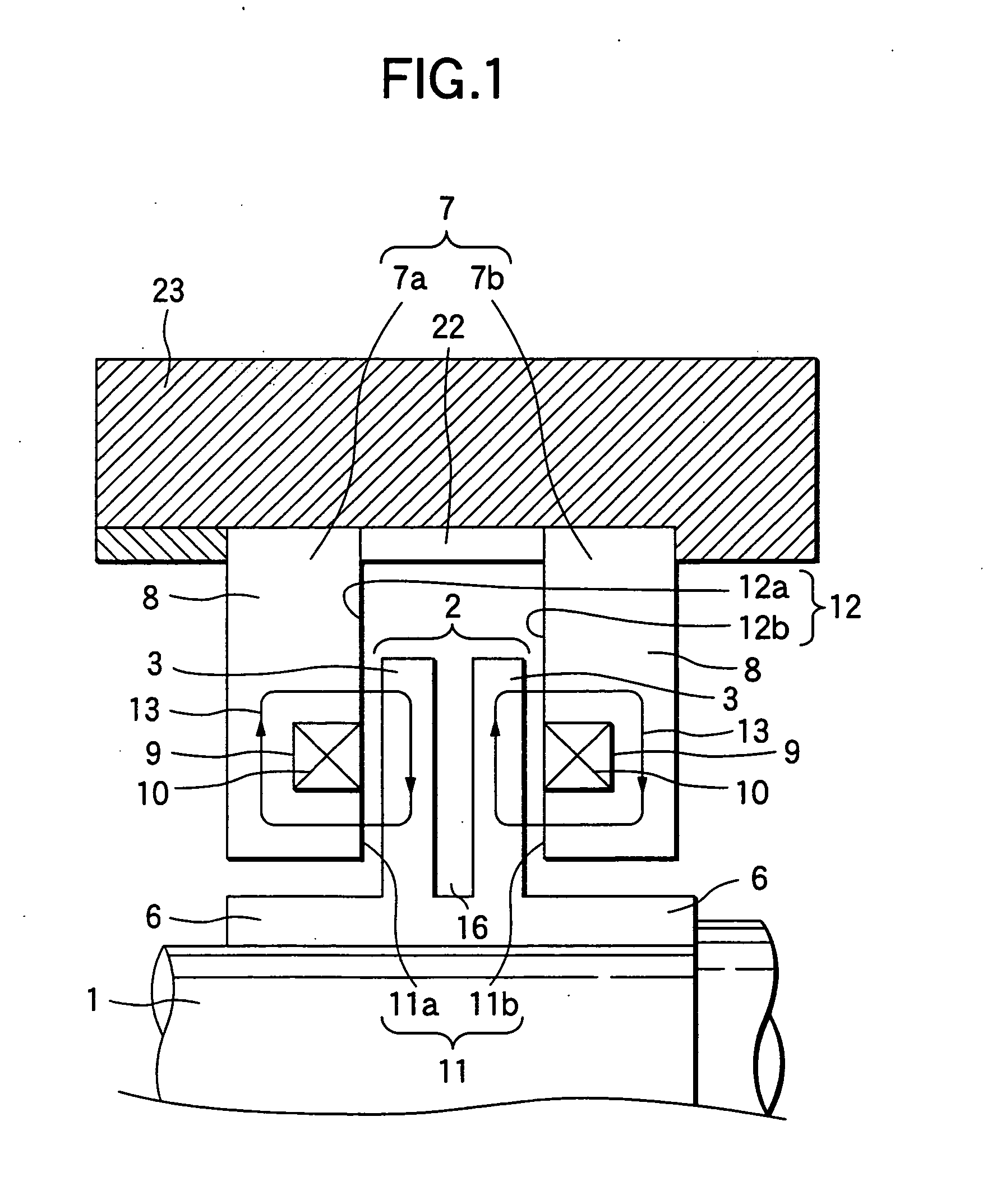
[0043]FIG. 1 is a sectional view showing Mode 1 for carrying out axial magnetic bearing apparatus according to the present invention. Ring-like coil slots 9 are formed symmetrically with respect to the rotation axes of ring-like housings 8 respectively formed out of a magnetic material which is superior in magnetic property. Ring-like electromagnetic coils 10 for generating magnetomotive force are inserted into the respective coil slots 9 so as to form electromagnetic stators 7 respectively. A rotary disc 2 made of a magnetic material is fixedly attached to a rotating shaft 1. The above-mentioned electromagnetic stators 7 are disposed respectively on opposite sides of the rotary disc 2 with suitable very small distances from the rotary disc 2. Sleeves 6 to be fixedly attached to the rotating shaft 1 are provided on opposite sides of the rotary disc 2. A deep...


PUM


Abstract

In axial magnetic bearing apparatus in which a rotary disc made of a magnetic material is fixedly attached to a rotating shaft, and electromagnets are disposed on opposite sides of the rotary disc so as to have suitable very small distances therefrom respectively, so as to bear the rotating shaft axially in a non-contact state, a deep groove for forming an air layer having large magneto-resistance is provided all over the outer circumference of the rotary disc. Thus, formation of a magnetic circuit not contributing to position control is relieved, and the weight of the disc is reduced so that the position control performance of the axial magnetic bearing and the natural frequency of a rotor are improved.

Description

TECHNICAL FIELD [0001] The present invention relates to axial magnetic bearing apparatus as follows. That is, in the axial magnetic bearing apparatus, a rotary disc made of a magnetic material is fixedly attached to a rotating shaft of rotating apparatus such as an electric generator, an electric motor, or the like. Electromagnetic stators each having an electromagnetic coil for generating magnetomotive force are fixed to casings respectively so as to be located with very small distances from the rotary disc. A displacement sensor for measuring axial displacement of the rotating shaft is provided. Magnetic attraction force is made to act between the rotary disc and the electromagnetic stators in accordance with an output signal from the displacement sensor, so as to bear the rotating shaft at a target position distant from the electromagnetic stators and in non-contact therewith. BACKGROUND ART [0002]FIG. 8 shows a background-art general example of so-called axial magnetic bearing a...

Claims


Application Information

Patent Timeline
Patent Type & Authority Applications(United States)
IPC IPC(8): F16C39/06H02K7/00H02K7/09
CPCF16C32/0461F16C37/005F16C32/0476F16C32/0468
Inventor SHIMADA, AKIHIRO
Owner MITSUBISHI ELECTRIC CORP
Features
  • R&D
  • Intellectual Property
  • Life Sciences
  • Materials
  • Tech Scout
  • Unparalleled Data Quality
  • Higher Quality Content
  • 60% Fewer Hallucinations
Learn More