Hinge connector for electronic device
a technology for electronic devices and hinges, applied in the direction of flexible/turnable line connectors, coupling contact members, coupling device connections, etc., can solve the problems of difficult installation of flex circuits in hinges, high cost, manual labor, etc., and achieve the effect of reliable us
- Summary
- Abstract
- Description
- Claims
- Application Information
AI Technical Summary
Benefits of technology
Problems solved by technology
Method used
Image

Examples
first embodiment
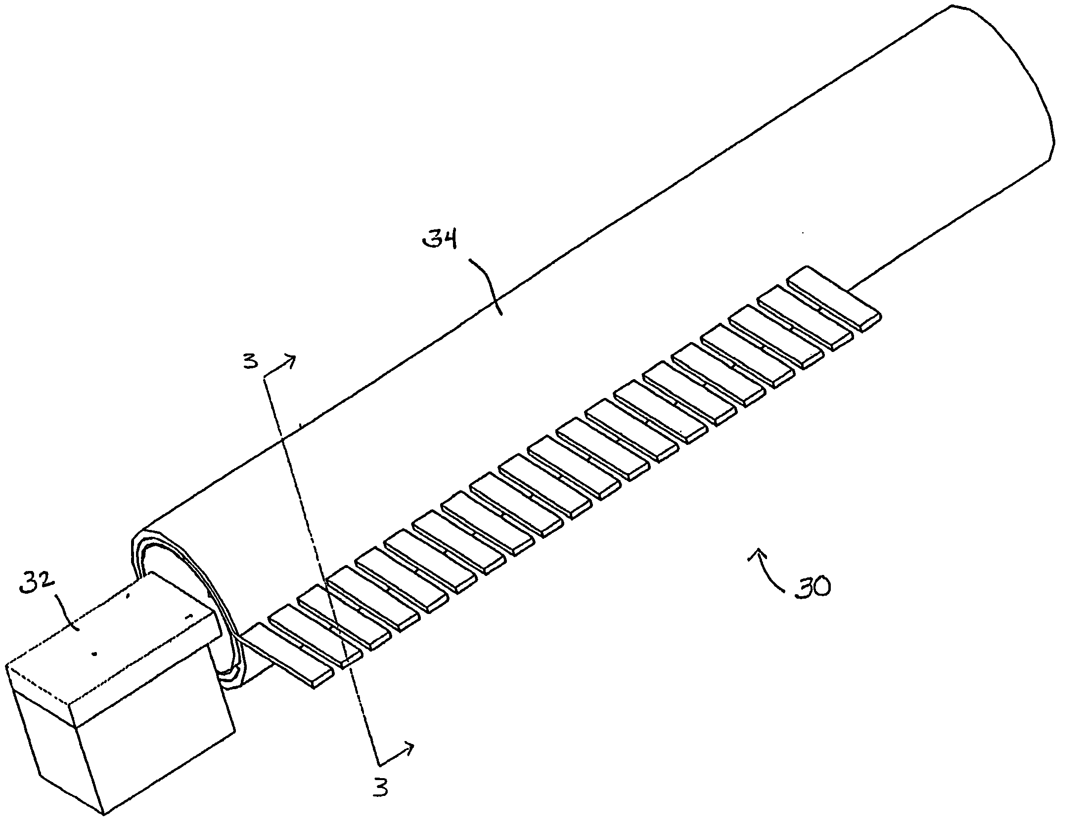
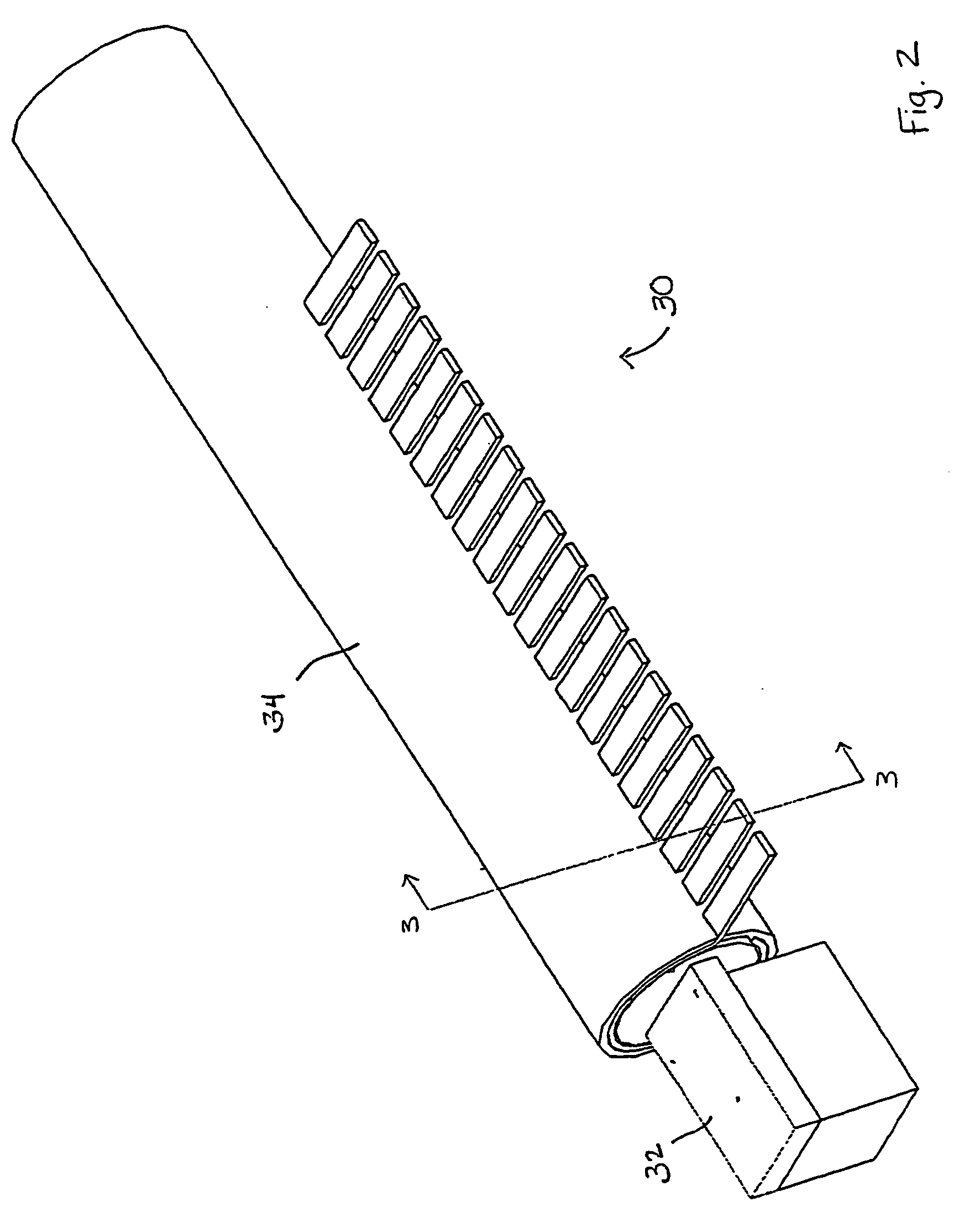
[0025] Attention is invited to the hinge 30 shown in FIGS. 2-7. As shown in FIGS. 2 and 3, the hinge 30 generally includes a body 32 and a contact member 34. The body 32 is partially positioned within the contact member 34 and partially extends from the contact member 34.
[0026] As best shown in FIG. 3, the body 32 includes a rectangularly-shaped printed circuit board 36, a plurality of spaced apart conductive terminals 38 extending from the printed circuit board 36, and a connector 40 extending from the printed circuit board 36. As best shown in FIG. 4, the body 32 also includes a generally cylindrically-shaped terminal sleeve 42.
[0027] The printed circuit board 36 has a first surface 44, a second surface 46, a proximal end 48 and a distal end 50. The terminals 38 extend perpendicularly from first surface 44 of the printed circuit board 36. Each terminal 38 includes a spring 52 and a ball 54. Each spring has opposite first 56 and second 58 ends. The first end 56 of each spring 52 i...
second embodiment
[0038] To assemble the body of the hinge, the terminal sleeve 42 is positioned such that the openings 70 are directed downward. Next, each ball 54 is passed through an opening 72, through the second portion 76 of a terminal passageway 68, passed the printed circuit board passageway 66, into the first portion 74 of the terminal passageway 68, and partially through the opening 70. Next, each spring 52 is passed through an opening 70, through the second portion 76 of the terminal passageway 68, past the printed circuit board passageway 66, and into the first portion 76 of the terminal passageway 68. Next, the printed circuit board 202 is placed within the printed circuit board passageway 66. With the printed circuit board 202 in place, the terminal sleeve 42 is rotated without displacing the balls 54 and springs 52 within the first portions 74 of the terminal passageways 68. Next, additional springs 52 are placed within the second portions 76 of the terminal passageways 68 and then bal...
third embodiment
[0041] The terminal sleeve of the third embodiment is generally tubularly-shaped and includes two diametrically opposed rows of openings. The circumference of each opening is dimensioned such that a portion of each ball extends through each opening.
[0042] To assemble the third embodiment of the hinge, the springs 322 are pre-loaded such that the first 302 and second printed circuit board 304 are moved toward one another. The printed first and second circuit boards 302, 304, along with the terminals 326, 328 mounted thereon, are placed within the tubularly-shaped terminal sleeve such that the terminals 326, 328 are aligned with the rows of openings. The pre-load on the springs 322 is then released such that the printed circuit boards 302, 304 are securely positioned within the terminal sleeve. The remainder of the hinge assembly is the same as the assembly of the first and second embodiments of the hinge.
PUM
 Abstract
Description
Claims
Application Information
 - R&D
- Intellectual Property
- Life Sciences
- Materials
- Tech Scout
- Unparalleled Data Quality
- Higher Quality Content
- 60% Fewer Hallucinations
Browse by: Latest US Patents, China's latest patents, Technical Efficacy Thesaurus, Application Domain, Technology Topic, Popular Technical Reports.
© 2025 PatSnap. All rights reserved.Legal|Privacy policy|Modern Slavery Act Transparency Statement|Sitemap|About US| Contact US: help@patsnap.com