Method of extracting contour of image, method of extracting object from image, and video transmission system using the same method
a contour extraction and image technology, applied in image data processing, image enhancement, instruments, etc., can solve the problems of large computation amount for a similar block search, inability to obtain high-quality composite images, and difficulty in extracting a target image part from an image at a high speed, so as to reduce the processing amount and high speed
- Summary
- Abstract
- Description
- Claims
- Application Information
AI Technical Summary
Benefits of technology
Problems solved by technology
Method used
Image

Examples
first embodiment
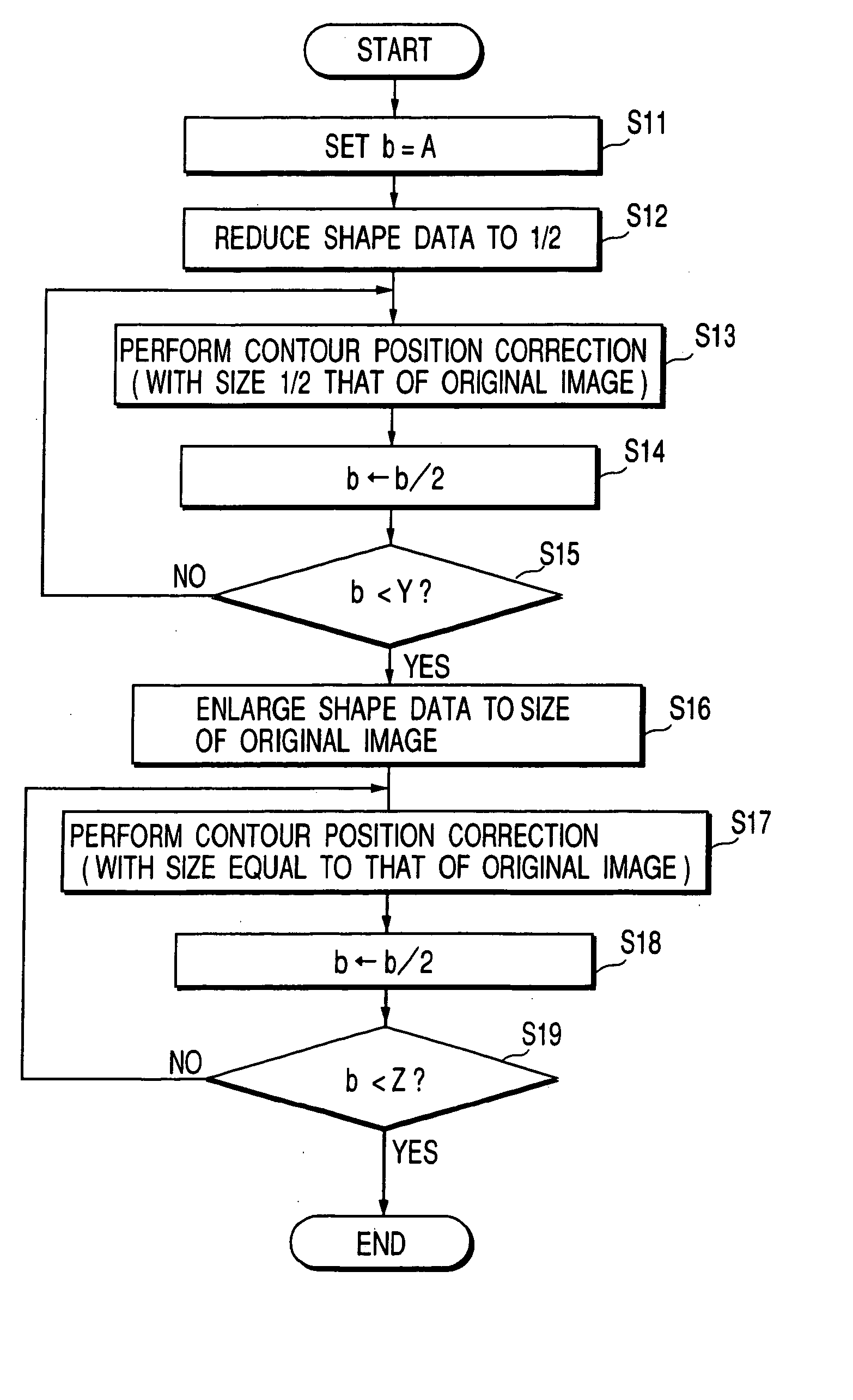
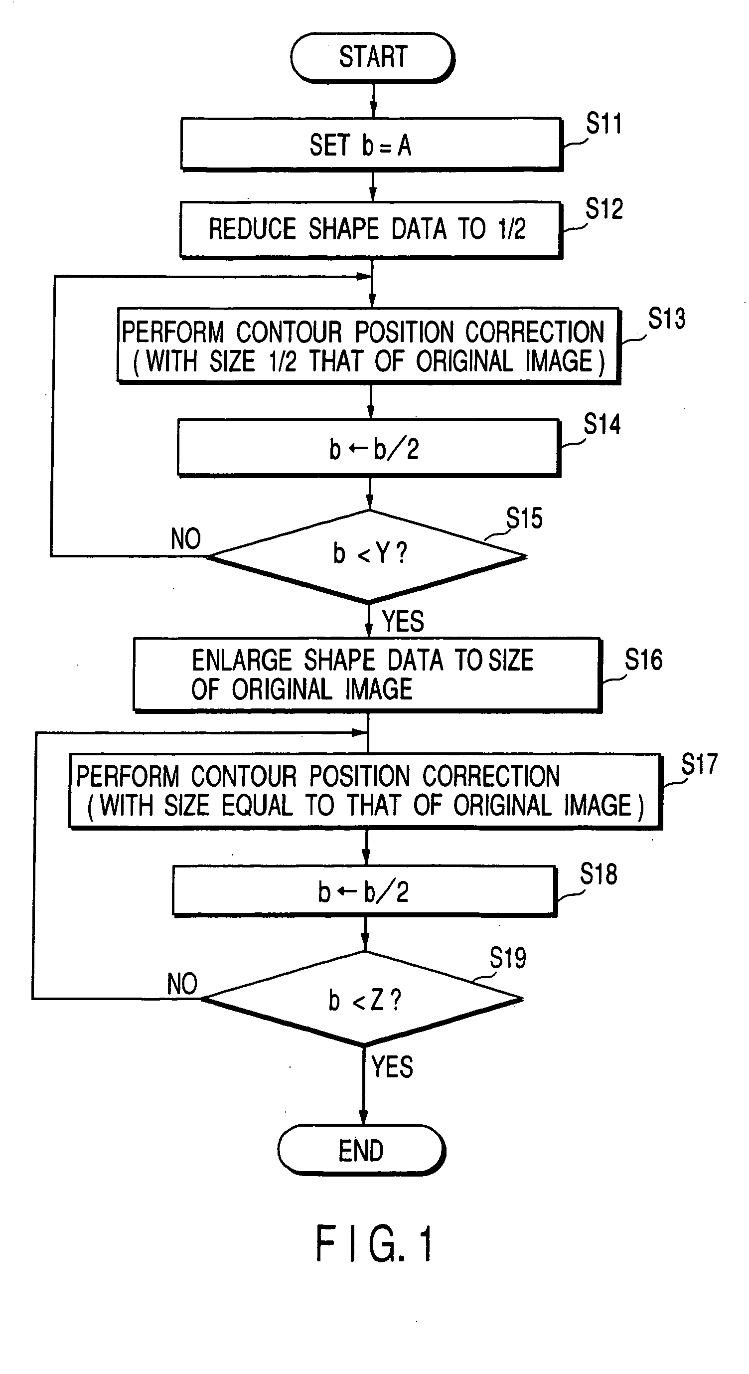
[0077] In the conventional technique, as shown in FIG. 9, shape data (alphamap), an original image (the frame image obtained by capturing an object), and each search reference block are used without changing their sizes (without any reduction). In contrast to this, in the present invention, to reduce the arithmetic processing load, processing proceeds with their sizes being reduced to half in the vertical and horizontal directions.
[0078] More specifically, assuming that the block size of one side of a search reference block is represented by b, b=A. The contour position correction described with reference to FIGS. 5 to 8 is performed by using search reference blocks each having the block size b=A, an original image (the frame image obtained by capturing an object), and shape data (alphamap) without changing their sizes. The block size b=A is then reduced to half. If the block size b is smaller than Z (<A), the processing is terminated. Otherwise, the block size is further reduced t...
second embodiment
[0115] An embodiment in which the similar block search ranges are switched in accordance with the direction of the contour of the shape data in a search reference block will be described.
[0116] As described with reference to FIG. 7, in the prior art, a similar block search range is determined by the position relative to a search reference block, but is not controlled by the position on the screen, shape data, and image data.
[0117] Assume that the contour of shape data crosses the inside of a search reference block like the search reference block B1 in FIG. 3. In this case, even if a search is made within a range Bs1′ obtained by expanding the similar block by W pixels vertically without expanding it horizontally, the expansion performance hardly deteriorates.
[0118] This is because, in the case of a similar block Bs1, an effect of correction can be obtained only by moving the contour of shape data vertically in replacement processing. In this case, the contour of the shape data is...
third embodiment
[0141]FIG. 10 is a flow chart for explaining a method of extracting an object from an image according to the third embodiment. In this embodiment, a statistical index termed separability is used. A separability S is expressed by the following equations (Fukui, “Object Contour Extraction Based on Separability between Regions”, PROCEEDINGS OF THE IEICE, D-II, Vol. J80-D-II, No. 6, pp. 1406-1414, 1997):
S=X / Y
X=Nb*(Ab−A)*(Ab−A)+Nf*(Af−A)*(Af−A)
where Nb is the number of pixels of a background region, Nf is the number of pixels of an object region, A is the average of all pixels, Ab is the average of the pixel values of the background, Af is the average of the pixel values of the object region, and Y is the sum of the squares of the differences calculated for all pixels in relation to the average A.
[0142] As is obvious from the above equations, as the difference between the average value of the object region and that of the background region increases, the separability approaches 1, w...
PUM
 Abstract
Description
Claims
Application Information
 - R&D
- Intellectual Property
- Life Sciences
- Materials
- Tech Scout
- Unparalleled Data Quality
- Higher Quality Content
- 60% Fewer Hallucinations
Browse by: Latest US Patents, China's latest patents, Technical Efficacy Thesaurus, Application Domain, Technology Topic, Popular Technical Reports.
© 2025 PatSnap. All rights reserved.Legal|Privacy policy|Modern Slavery Act Transparency Statement|Sitemap|About US| Contact US: help@patsnap.com