Supercharge Your Innovation With Domain-Expert AI Agents!

RFID tag and method of user verification

a technology of user verification and user identification, applied in the field of human interaction with secure computer systems, can solve the problems of reducing reducing the risk, and consuming time, so as to reduce the risk and increase the functionality of the system

Inactive Publication Date: 2005-08-11
SCRIPTPRO LLC
View PDF99 Cites 4 Cited by
  • Summary
  • Abstract
  • Description
  • Claims
  • Application Information

AI Technical Summary

Benefits of technology

Enhances security and efficiency by eliminating manual login procedures, reducing the risk of unauthorized access, and allowing simultaneous use of keyboards and touch screens without impeding hand functionality.

Problems solved by technology

Operators of such systems, however, often spend only a portion of their time at the systems.
This can become time consuming, and may open the door to security breaches if the user forgets to log out.
Use of identification numbers and badges is not only inconvenient, but also introduces the risk of an unauthorized user obtaining an identification number and / or badge and accessing the system, thus compromising security.
Unfortunately, fingertip pointers often impede other uses of the hand or finger, such as typing or writing.
The evolution of computers has created special demands for screen navigation tools that are not adequately met by current touch screen pointers.
Furthermore, portable computing devices, such as notebook computers and personal digital assistants (PDAs), present a unique challenge because their limited size and resources prohibit use of the more robust user input devices available to stationary computer systems.
Unfortunately, traditional pointers are not well adapted to meet the needs of these situations, as hand-held pointers can be prohibitively cumbersome and inefficient and finger-mounted pointers can impede use of the hand.

Method used


Image

  • RFID tag and method of user verification
  • RFID tag and method of user verification
  • RFID tag and method of user verification

Examples


Embodiment Construction

, below.

BRIEF DESCRIPTION OF THE DRAWINGS

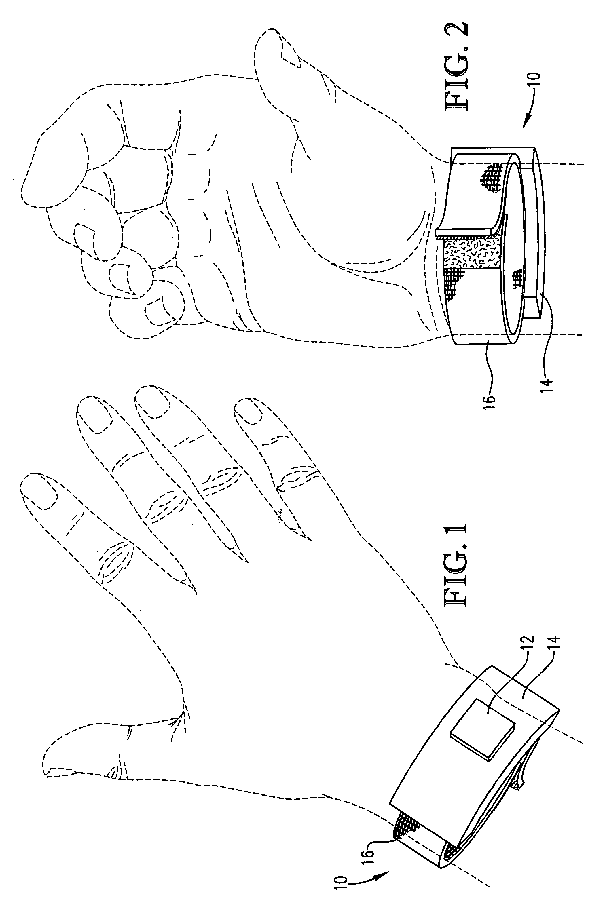
[0023]FIG. 1 is a top view of an RF identification tag secured to a user's wrist according to a preferred embodiment of the present invention;

[0024]FIG. 2 is a bottom view of the tag of FIG. 1 secured to a user's wrist;

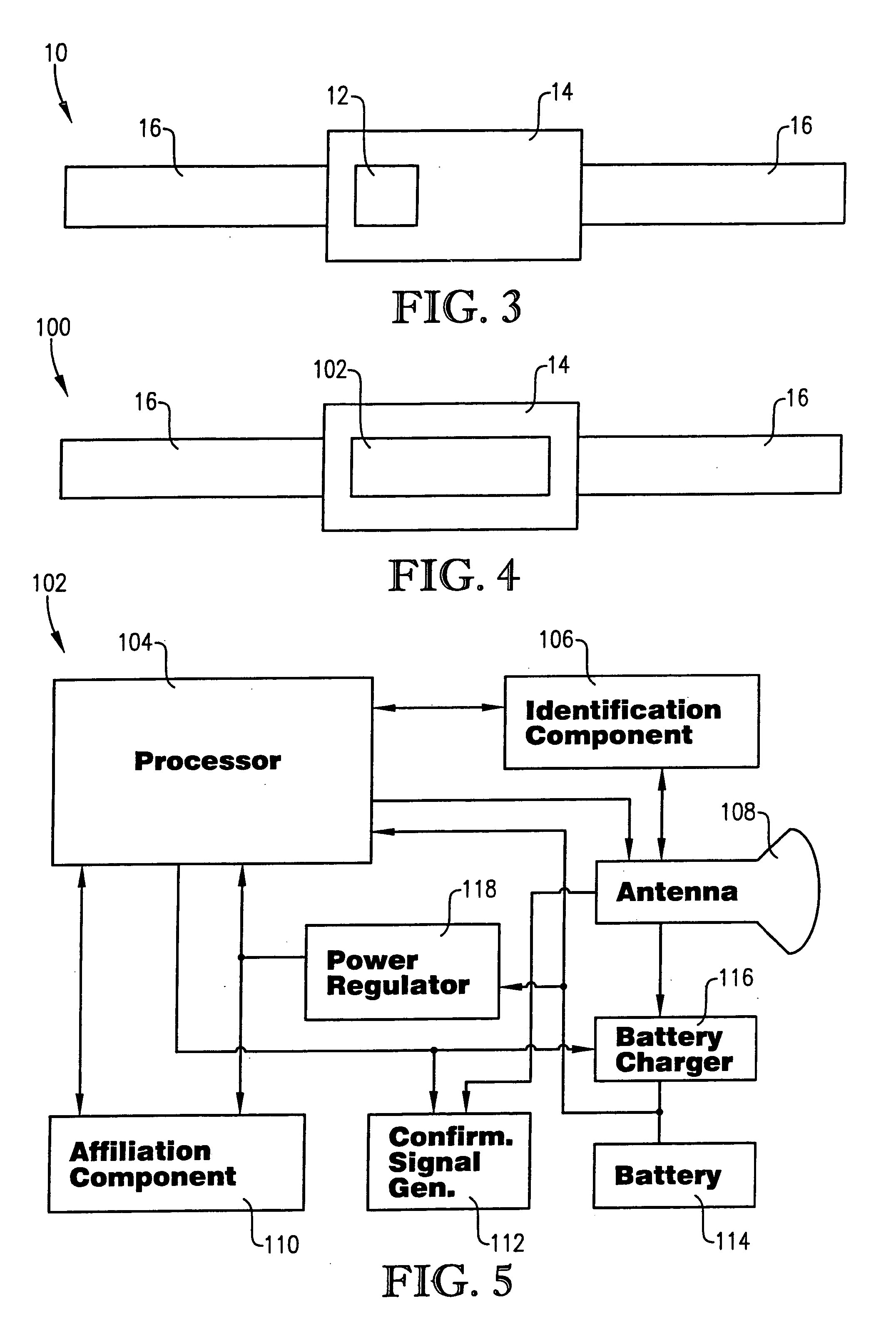
[0025]FIG. 3 is a schematic of components of the tag of FIG. 1;

[0026]FIG. 4 is a schematic of components of an alternate embodiment of the RF identification tag of the present invention;

[0027]FIG. 5 is a schematic of components of an identification and registration circuit of the RF identification tag of FIG. 4;

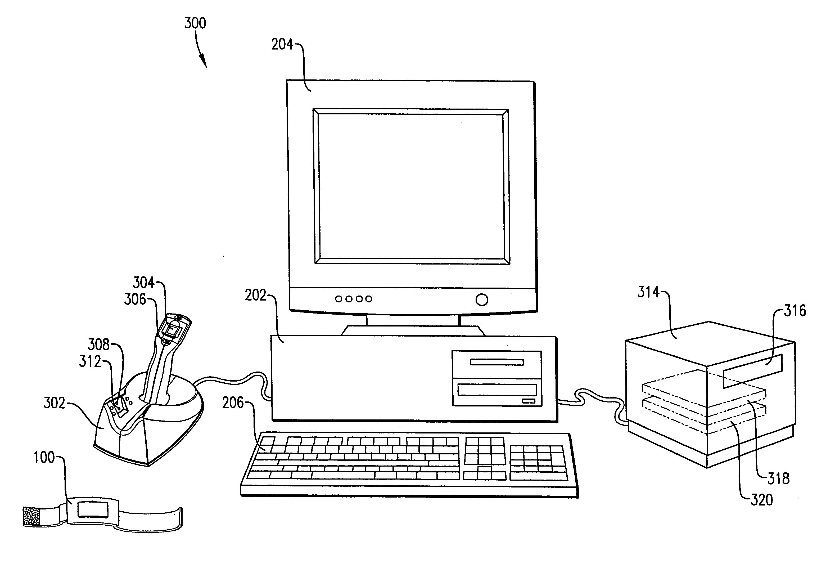
[0028]FIG. 6 is a perspective view of the RF identification tag of FIG. 1 used with another embodiment of the present invention;

[0029]FIG. 7 is a perspective view of the RF identification tag of FIG. 4 used with another embodiment of the present invention;

[0030]FIG. 8 is a perspective view of an RF identification tag registration device of the computer system of FIG. 7, illustrating a placement of a user's hand o...


PUM


Abstract

An identification tag (100) facilitates use of a secure computer system (300). The tag (100) is adapted to be worn on a user's wrist and includes an identification and registration circuit (102) that includes an identification component (106), an affiliation component (110), and a light-emitting diode (112). The computer system includes an RF identification tag registration device (302) operable to acquire user physical information and communicate the physical information to a computer (202), wherein the computer verifies that a valid user is wearing the tag (100). The identification and registration device (302) ensures that the physical information communicated to the computer pertains to the user wearing the tag by comparing pulse signals acquired from the user's hand and wrist as the device (302) is acquiring physical information. The computer (202) uses the identification information and the affiliation information to log the user into and out of the system (300), and to associate the identification information with a particular user.

Description

RELATED APPLICATIONS [0001] The present application is a continuation and claims priority benefit, with regard to all common subject matter, of an earlier-filed U.S. patent application titled “RFID TAG AND METHOD OF USER VERIFICATION”, Ser. No. 10 / 869,597, filed Jun. 16, 2004, which claims priority benefit, with regard to all common subject matter, of earlier-filed U.S. provisional patent applications entitled “SMART TOUCH SCREEN POINTER,” Ser. No. 60 / 479,752, filed Jun. 19, 2003; “USER VERIFICATION FOR SMART TOUCH SCREEN POINTER,” Ser. No. 60 / 483,012, filed Jun. 26, 2003; and “SMART TOUCH SCREEN POINTER,” Ser. No. 60 / 484,495, filed Jul. 2, 2003. The above-identified non-provisional and provisional applications are hereby incorporated by reference into the present application. The present application also relates to co-pending U.S. application Ser. No. 10 / 869,596, filed Jun. 16, 2004, entitled “RFID TAG AND METHOD OF USER VERIFICATION” and U.S. application Ser. No. 10 / 869,595, filed...

Claims


Application Information

Patent Timeline
Patent Type & Authority Applications(United States)
IPC IPC(8): G06K5/00
CPCG06F3/03543G06F2203/0336G06F2203/0334G06F21/34
Inventor COUGHLIN, MICHAEL E.KNUTSEN, BERNHARD P.SCHLOEMER, DAVID E.
Owner SCRIPTPRO LLC
Features
  • R&D
  • Intellectual Property
  • Life Sciences
  • Materials
  • Tech Scout
  • Unparalleled Data Quality
  • Higher Quality Content
  • 60% Fewer Hallucinations
Learn More