Check patentability & draft patents in minutes with Patsnap Eureka AI!

Pressure monitor incorporating saw device

a pressure monitor and saw device technology, applied in the direction of piezoelectric/electrostrictive devices, instruments, electrical apparatus, etc., can solve the problems of mechanical edge, change in output of the saw device, and the difficulty of clamping the edge of the diaphragm, so as to reduce the number and size of defects, and eliminate any stress raiser

Inactive Publication Date: 2005-10-13
TRANSENSE TECH
View PDF8 Cites 3 Cited by
  • Summary
  • Abstract
  • Description
  • Claims
  • Application Information

AI Technical Summary

Benefits of technology

[0015] Conventionally, quartz planar components are produced by grinding and lapping operations, which results in a large number of small defects on the surfaces thereof whose size is characteristic of the grinding and lapping processes. The compressed surface of the component is then finished by polishing so as to facilitate deposition of metal thereto to form the various components of the SAW device. Traditionally, however, the tensioned surface has not been so finished for two reasons: firstly, because the extra cost involved in polishing both surfaces of the component was deemed unnecessary, and secondly, because the unpolished surface was found to suppress reflection of the bulk wave during operation of the SAW device, thereby reducing parasitic losses which result from those reflections.
[0016] It has, therefore, been found that the bending strength of the SAW devices can be significantly improved if opposing surfaces of the component are polished so as to reduce the number and of size of the defects in the surface, that is both the surface upon which metal is deposited to form components of the SAW device and which, upon bending of the device during use, will be under compression, and the opposite surface thereof which, upon bending of the device in use, will be tensioned, both said first and second surfaces being polished.
[0017] Further improvements may advantageously be achieved by also polishing the edges of the SAW device in order to eliminate any stress raisers resulting from the cutting of the device from the wafer.
[0018] The SAW devices in the invention may be glued in place by using conventional adhesives, but the mechanical properties of the pulling bond have been found to reduce the responsiveness and sensitivity of SAW devices. Instead, therefore, it has been found to be advantageous to fasten the SAW devices by soldering, which may be achieved by providing a metallization layer on the bonding surface of the substrate of the device. Soldering has the advantage of greatly improving the transfer of strain and thermal properties of the transducer, and hence improves the accuracy and sensitivity of a SAW.
[0020] This has the advantage of bonding well to the metalized layer, particular if a multi-metallic coating is applied to the bonding surface of the SAW with the outer coating thereof being gold, and couples the SAW particularly effectively to the stress field of the structural component which it is intended to measure due to the high stiffness (68 GPa) and strength (275 MPa tensile) of AuSn enabling it to act as a good strain transfer medium.
[0021] Unlike a conventional polymeric backed foil strain gauge, single crystal quartz is a stiff material (80 GPa), and the stress levels required successfully to transmit strain from a structural member formed of, for example, steel, in a quartz SAW device are necessarily high. As a result, creep will manifest itself at much lower temperatures if a conventional strain gauge adhesive, such as M BOND 610™, is used. The use of AuSn, in contrast, results in much lower levels of creep and hysteresis at the high temperatures, which can be up to 125 degrees centigrade, typically encountered in automotive applications.

Problems solved by technology

However, mechanical edge effects associated with clamping the edge of the diaphragm considerably complicate interpreting the signal receiver from the SAW device.
Accordingly, deflection of the lid acting as a diaphragm will cause bending of the SAW device with a resulting change in output of the SAW device.
Any pre-existing defect which exists in the surface under tension will, then, be an area of weakness and hence likely to be the initial source of any failure of the component under bending.
The failure strength under bending will, therefore, be limited by the size of the largest pre-existing defect in the component.
Conventionally, quartz planar components are produced by grinding and lapping operations, which results in a large number of small defects on the surfaces thereof whose size is characteristic of the grinding and lapping processes.
Traditionally, however, the tensioned surface has not been so finished for two reasons: firstly, because the extra cost involved in polishing both surfaces of the component was deemed unnecessary, and secondly, because the unpolished surface was found to suppress reflection of the bulk wave during operation of the SAW device, thereby reducing parasitic losses which result from those reflections.
The SAW devices in the invention may be glued in place by using conventional adhesives, but the mechanical properties of the pulling bond have been found to reduce the responsiveness and sensitivity of SAW devices.
As a result, creep will manifest itself at much lower temperatures if a conventional strain gauge adhesive, such as M BOND 610™, is used.
The use of AuSn, in contrast, results in much lower levels of creep and hysteresis at the high temperatures, which can be up to 125 degrees centigrade, typically encountered in automotive applications.

Method used


Image

  • Pressure monitor incorporating saw device
  • Pressure monitor incorporating saw device
  • Pressure monitor incorporating saw device

Examples


Embodiment Construction

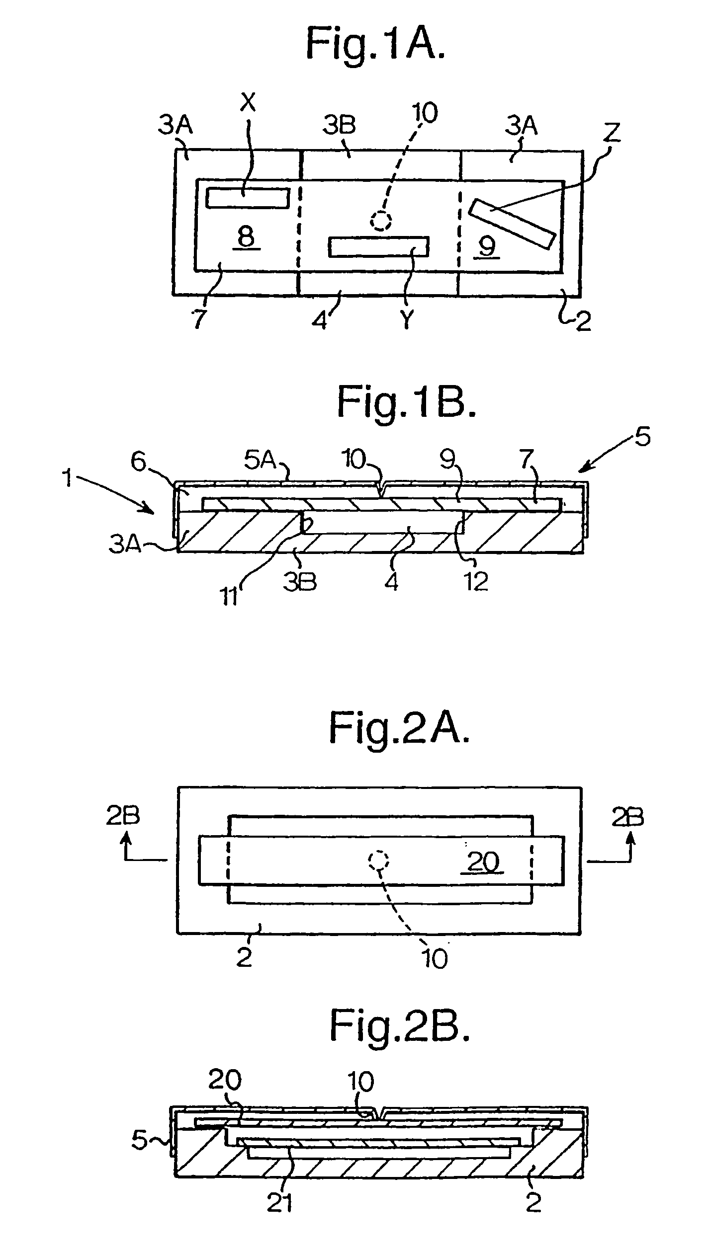
[0035] Referring firstly to FIGS. 1A and 1B, there is shown schematically a pressure monitor 1 comprising a base 2 having rigid frame 3A and a rigid base 313 which together define a shallow rectangular container 4. The container 4 may be formed of any suitable material, and in the preferred embodiment of the invention is formed of a metal material, for example KOVAR™. The container 4 has secured to the open end thereof a lid 5 having a major surface 5A acting as a diaphragm. The lid may be of any suitable material, for example KOVAR™. Both the material from which the base is made and the material from which the lid acting as a diaphragm is made are preferably impermeable to gas and the seal between the lid and the base is also preferably impermeable to gas. The seal between the lid in the base may be formed by any convenient means. If both the lid and the base are of suitable metal alloys, the seal therebetween may be formed by a soldering process. When the lid 5 acting as a diaphra...


PUM


Abstract

A pressure monitor has a base and a lid secured to the base to define a substantially fluid tight chamber. At least part of the lid is flexible and forms a diaphragm which deflects responsive to changes in fluid pressure surrounding the monitor. A projection provided on the diaphragm transmits movement thereof to a distortable substrate located within the chamber. A first SAW device is mounted on the distortable substrate, and at least a second and third SAW device are mounted within the chamber. The second SAW device carried on a reference substrate section has its direction of propagation inclined at an angle to the direction of propagation of at least one of the first and third SAW devices. This way movement of the diaphragm induced by a change in pressure in the zone surrounding the monitor results in distortion of the distortable substrate, which is measurable by the SAW device mounted thereon, without distorting said reference substrate section.

Description

FIELD OF INVENTION [0001] This invention relates to a pressure monitor incorporating a SAW device. DESCRIPTION OF THE RELATED ART [0002] Pressure monitors incorporating SAW devices have been proposed, for example in our United Kingdom patent application GB-A-2352814. The SAW devices are used to produce an electrical signal indicative of the position of a pressure sensitive member, for example a diaphragm, which is used to divide a chamber containing a reference pressure from a chamber which is subject to a variable pressure. The present invention relates to an improved pressure monitor of this type. GB 2235533 discloses a piezoelectric sensor device in which a surface acoustic wave device is mounted on a flexible diaphragm which is supported around its periphery by an integral rigid assembly. Displacement of the diaphragm, for example in response to an applied pressure, induces a strain in the piezoelectric material thus causing a corresponding change in the characteristic frequency...

Claims


Application Information

Patent Timeline
IPC IPC(8): G01L1/16G01L9/00G01L19/00
CPCG01L1/165G01L9/0025G01L19/0092
Inventor KALININ, VICTOR ALEXANDROVICHLEE, MARKLOHR, RAYMOND DAVIDLEIGH, ARTHUR JOHN
Owner TRANSENSE TECH
Features
  • R&D
  • Intellectual Property
  • Life Sciences
  • Materials
  • Tech Scout
  • Unparalleled Data Quality
  • Higher Quality Content
  • 60% Fewer Hallucinations
Learn More