Check patentability & draft patents in minutes with Patsnap Eureka AI!

Low profile fusion cage and insertion set

a fusion cage and low profile technology, applied in the field of low profile fusion cage and insertion set, can solve the problems of difficulty or unfavorable implementation of a pair of implants that otherwise have desirable dimensions and attributes, none achieve optimum performance, versatility or ease of insertion, etc., to facilitate the close insertion and placement of implants.

Inactive Publication Date: 2005-10-13
HOWMEDICA OSTEONICS CORP
View PDF48 Cites 4 Cited by
  • Summary
  • Abstract
  • Description
  • Claims
  • Application Information

AI Technical Summary

Benefits of technology

[0005] In a preferred embodiment, a fusion implant according to the present invention is provided with a concave cut-away portion on a circumferential surface of an elongated implant. The concave portion accommodates the outer contour of an adjacently placed implant having a corresponding concave surface. A novel dual tang distractor tool is provided with two over-lapping cross-sectional configurations to facilitate close insertion and placement of implants according to the present invention.

Problems solved by technology

Because of limited space for implantation and for surgical maneuvering, it is sometimes difficult or unfeasible to implement a pair of implants that otherwise have desirable dimensions and attributes.
Certain existing implant designs are configured for close, adjacent placement to other implants, but none achieve optimum performance, versatility or ease of insertion.

Method used


Image

  • Low profile fusion cage and insertion set
  • Low profile fusion cage and insertion set
  • Low profile fusion cage and insertion set

Examples


Embodiment Construction

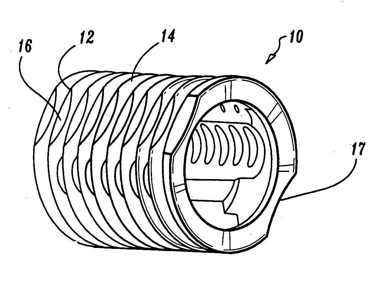
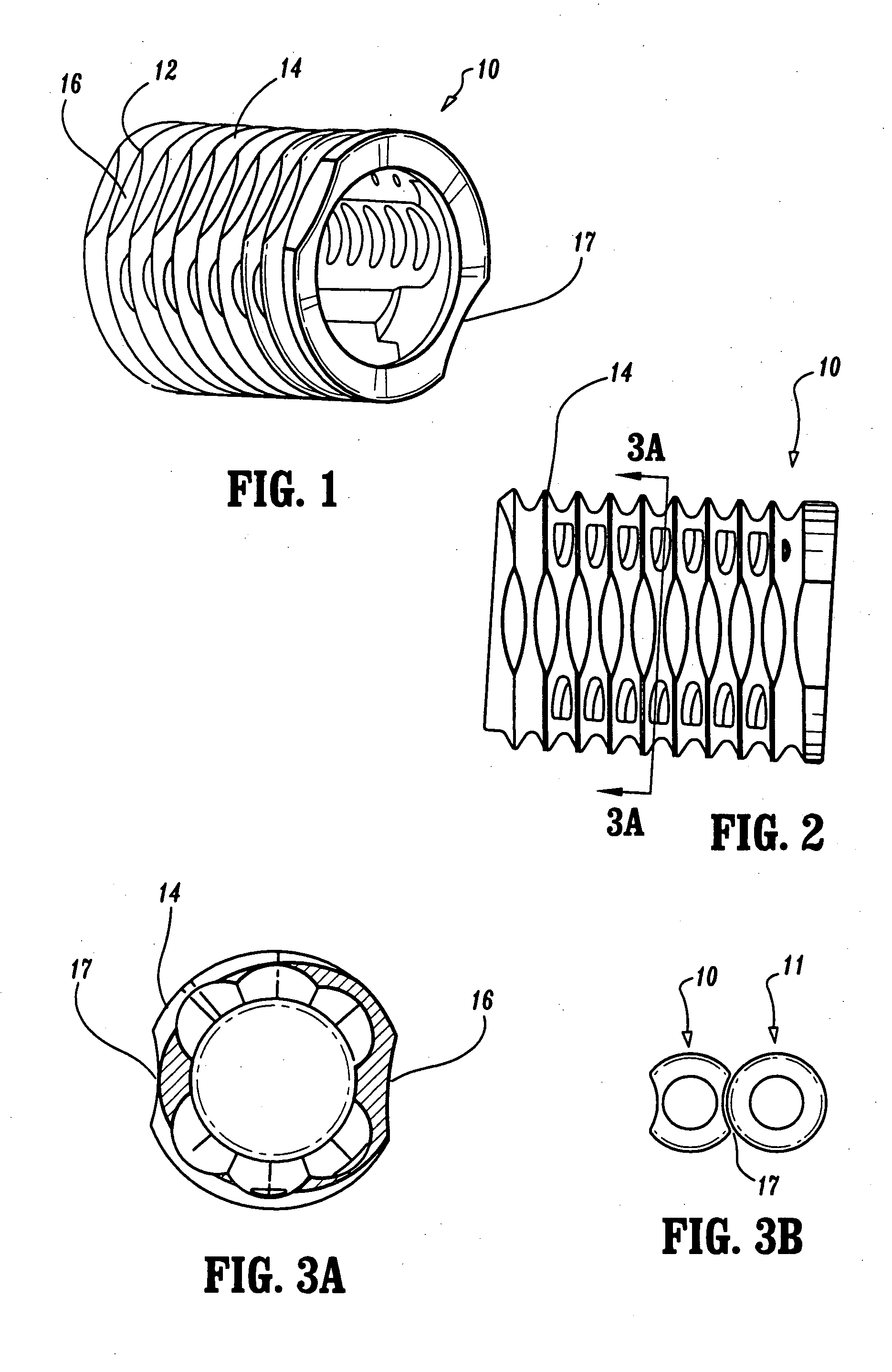
[0017]FIGS. 1-3a illustrate perspective, side and end views of the low profile fusion cage (10) of the present invention. The present invention cage (10) is of the type known commercially as the Ray TFC™ Fusion Cage currently marketed by Surgical Dynamics, Inc. The Ray TFC™ Fusion Cage is disclosed in commonly assigned U.S. Pat. No. 4,961,740, the contents of which are incorporated herein by reference.

[0018] The fusion cage (10) disclosed herein can be implemented with another fusion cage to reduce the total amount of space occupied by two conventional fusion cages placed side by side. The fusion cage (10) has a helical thread (14) for facilitating insertion and securing of the cage (10) in a vertebral disc space. The thread (14) is carved out to form concave portions (16, 17) to reduce the profile of the thread. As shown, the concave portions (16, 17) are preferably provided 180 degrees apart. If desired, only one concave portion is necessary to carry out the present invention. It...


PUM


Abstract

A bone fusion implant system including a first implant body having substantially flat top and bottom surfaces for engaging opposing vertebrae and a side wall extending between the top and bottom surfaces, the side wall including a concave recess and a second implant body having substantially flat top and bottom surfaces for engaging the opposing vertebrae and a side wall extending between the top and bottom surfaces thereof, the side wall of the second implant including an arcuate portion adapted to be received within the concave recess for enabling the first and second implant bodies to be positioned in nested side-by-side relation between the opposing vertebrae.

Description

CROSS REFERENCE TO RELATED APPLICATIONS [0001] The present application is a continuation of U.S. patent application Ser. No. 10 / 338,463, filed Jan. 8, 2003, now allowed, which is a divisional of U.S. patent application Ser. No. 09 / 545,320, filed Apr. 7, 2000, now U.S. Pat. No. 6,783,545, which claims benefit of U.S. Provisional Application No. 60 / 128,113, filed Apr. 7, 1999. The disclosures of the '463, '320 and '113 applications are hereby incorporated by reference herein.BACKGROUND OF THE INVENTION [0002] The present application relates to a low profile fusion cage and an insertion set for the low profile fusion cage. [0003] Known spinal implants, such as those used for vertebral fusion, are often used in pairs to provide adequate, evenly distributed support and fusion inducement. Because of limited space for implantation and for surgical maneuvering, it is sometimes difficult or unfeasible to implement a pair of implants that otherwise have desirable dimensions and attributes. Ce...

Claims


Application Information

Patent Timeline
Patent Type & Authority Applications(United States)
IPC IPC(8): A61B17/02A61B17/56A61B17/17A61F2/00A61F2/28A61F2/30A61F2/44A61F2/46
CPCA61B17/1757A61F2310/00179A61F2/442A61F2/446A61F2/4611A61F2002/2835A61F2002/30131A61F2002/302A61F2002/30235A61F2002/30611A61F2002/30616A61F2002/30747A61F2002/30785A61F2002/30787A61F2002/3082A61F2002/3085A61F2002/30858A61F2002/4475A61F2002/448A61F2002/4681A61F2230/0013A61F2230/0065A61F2230/0069A61F2250/0063A61F2310/00017A61F2310/00023A61B2017/0256A61F2002/30604A61F2/30744A61F2002/30593
Inventor CASTRO, SALVATOREMCDONNELL, CHRISTOPHER
Owner HOWMEDICA OSTEONICS CORP
Features
  • R&D
  • Intellectual Property
  • Life Sciences
  • Materials
  • Tech Scout
  • Unparalleled Data Quality
  • Higher Quality Content
  • 60% Fewer Hallucinations
Learn More