Filter device for fluids and method for filtering fluids

Active Publication Date: 2006-02-09
RASSINGER GUENTHER
View PDF40 Cites 20 Cited by
  • Summary
  • Abstract
  • Description
  • Claims
  • Application Information

AI Technical Summary

Benefits of technology

[0018] The invention achieves advantages associated with the fact that the filter capacity for particles and contaminants is extensively exploited, including in particular the filter's capacity to absorb water, which results in the inventive filter device having a filter service life which, in comparison with filter assemblies containing identically large filters, for motor oils, are longer by at least a factor of greater than 1, preferably 2-3 times or larger, and for hydrauli

Problems solved by technology

Particles such as these cause damage to engines, pumps, controls, regulators, so that such systems age more quickly due to mechanical wear and corrosion.
Even liquid media such as motor oil, transmission oil, hydraulic oil, transformer oil, petroleum and synthetic oils and mixtures, mineral oils, partially and completely biological oils or their mixtures, and completely synthetic oils cause wear due to such particles and become contaminated more quickly.
If the particles and contaminants are not filtered out, the systems can experience clogging or adhesive lock since the liquid media, such as the diverse oils specified above, can thicken due to accumulation of particles and/or the formation of an emulsion, i.e. its viscosity increases and, hence, a high degree of friction is created in lubricating slots

Method used


Image

  • Filter device for fluids and method for filtering fluids
  • Filter device for fluids and method for filtering fluids
  • Filter device for fluids and method for filtering fluids

Examples


Embodiment Construction

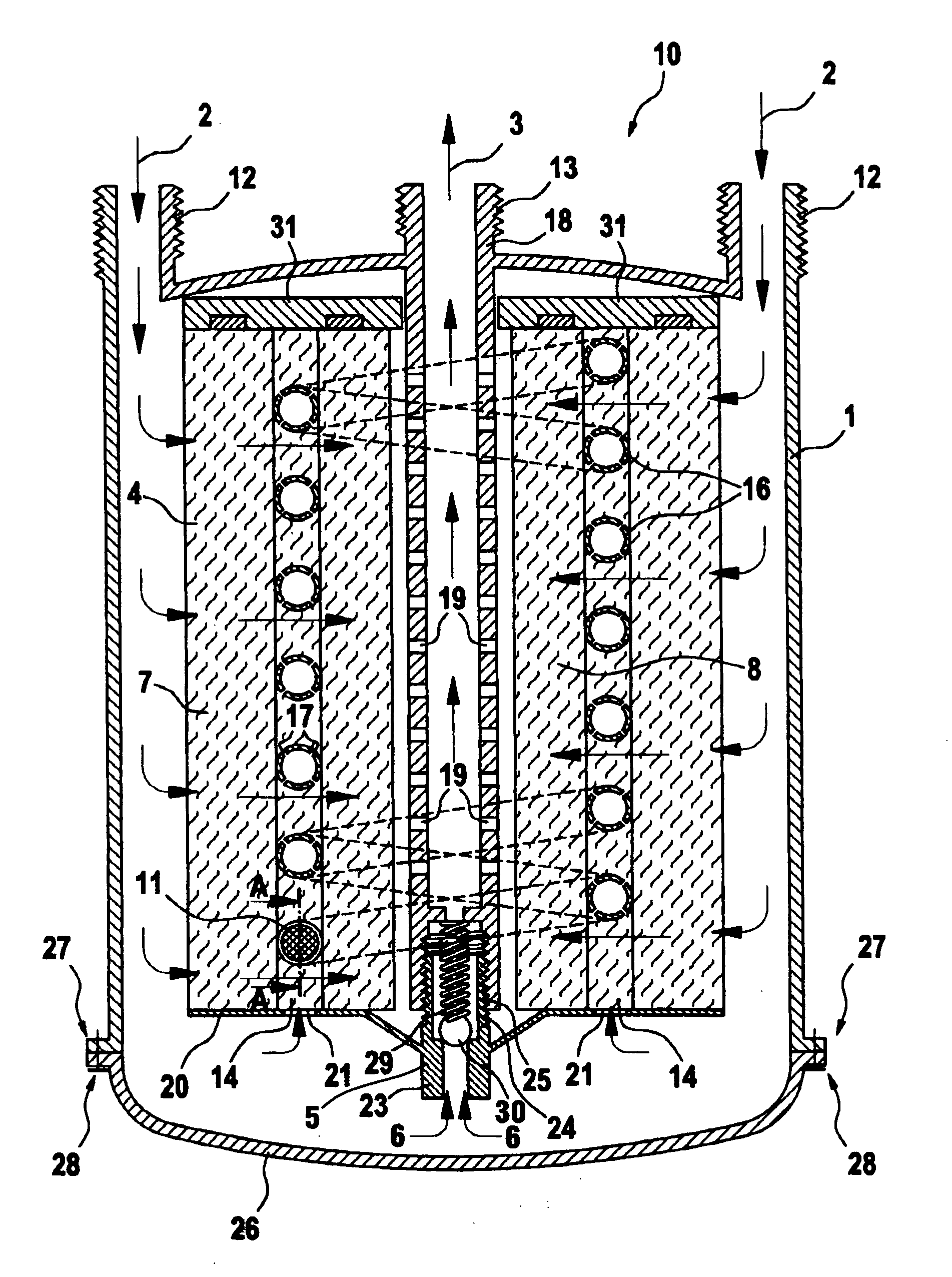
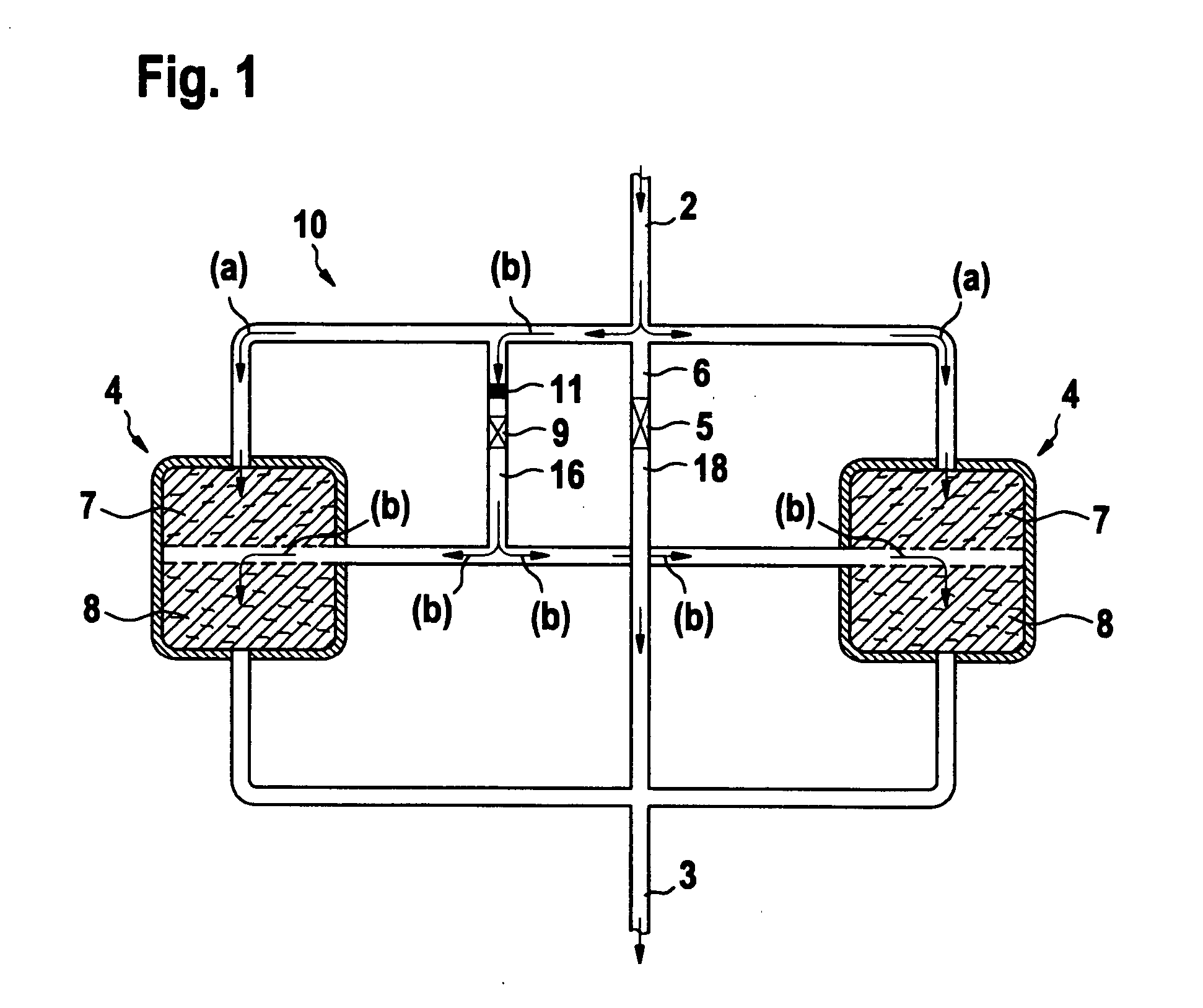
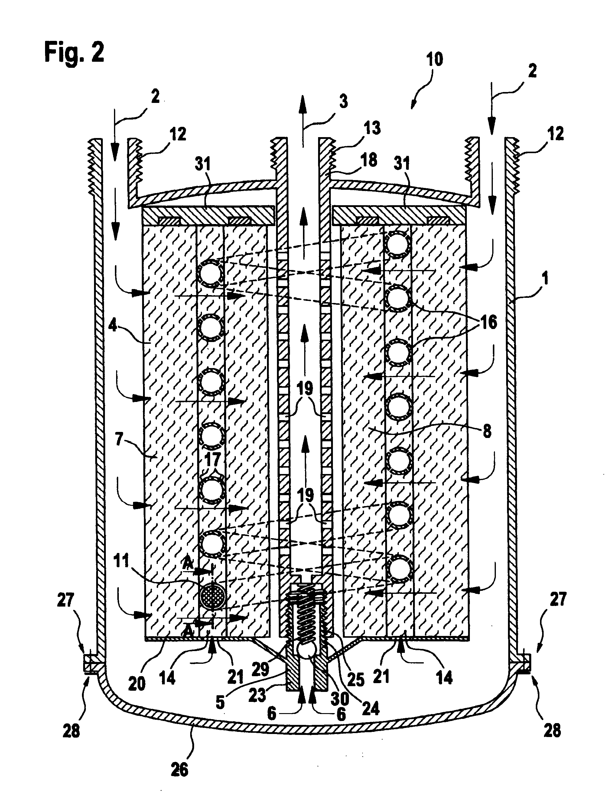
[0027] A filter device 10, shown schematically in cross-section in FIG. 1, is arranged in a closed circulation system which involves motor oil, hydraulic oil, other oil or other fluid, for an excavator, for example. Filter device 10 includes a filter inlet 2, a filter outlet 3 and an intermediary filter 4, consisting of an outer filter element 7 and an inner filter element 8. The filter elements 7, 8 are designed in a ring shape and arranged concentrically around a central tube 18 of a filter device 10. The intermediary filter 4 is schematically split up in two parts, each having the reference numeral 4, for better understanding the function of the filter device 10 as described thereafter. It is to imagine that one part is arranged left from the tube 18 and the other part of filter 4 is right from tube 18. A duct 16, in which a sieve 11 is positioned upstream from a pressure-controlled regulating valve 9, by-passes one part of filter 4, specifically the outer filter element 7, and r...


PUM

PropertyMeasurementUnit
Fractionaaaaaaaaaa
Fractionaaaaaaaaaa
Diameteraaaaaaaaaa

Abstract

A filter device 10 for fluids, especially for motor oil, hydraulic oil, has a filter case 1 comprising one or two filter inlets 2 and one filter outlet 3. The filter case contains one filter 4 consisting of at least two ring-shaped filter elements 7, 8 which concentrically enclose a central tube 18 of the filter device. In a channel 14 between the two adjacent filter elements there is a duct 16 which is run in the form of a spiral around inner filter element 8 and is embedded in filter 4. In duct 16 there is a pressure-controlled regulating valve 9 which opens when a certain level of pressure is exceeded in the filtered oil.

Description

BACKGROUND OF THE INVENTION [0001] 1. Field of the Invention [0002] The invention relates to a filter device for fluids, including a filter case containing at least one filter inlet and one filter outlet and one filter arranged in between. The device includes a duct for by-passing a portion of the filter, and a valve for by-passing the entire filter. The invention also relates to a method for filtering fluids through a filter, including the steps of introducing a fluid, filtering the fluid until the pressure across the filter reaches a first limit, by-passing a portion of the filter while continuing filtering the fluid, and by-passing the filter entirely when the pressure across the filter reaches a second limit. The first and second limit may be the same or different. [0003] 2. Prior Art [0004] Particles of various sizes and consistency which collect in liquid and gas media used for lubricating and / or cooling moving machine parts as a result of wear, corrosion, contamination and re...

Claims


Application Information

Patent Timeline
IPC IPC(8): B01D35/147
CPCB01D29/114B01D35/147B01D29/54B01D29/58
Inventor RASSINGER, GUENTHER
Owner RASSINGER GUENTHER
Why Eureka
Try Eureka