Multi-mode antenna and multi-band antenna combination

a multi-mode antenna and antenna combination technology, applied in the direction of resonant antennas, elongated active elements feeding, radiating element structural forms, etc., can solve the problems of trouble-prone and unreliable use of positioning members, inability to achieve the performance of a desired multi-band antenna, and inability to tune the antenna b>1/b> to a plurality of resonant frequencies during operation

Active Publication Date: 2006-03-09
INVENTEC APPLIANCES CORP
View PDF7 Cites 53 Cited by
  • Summary
  • Abstract
  • Description
  • Claims
  • Application Information

AI Technical Summary

Benefits of technology

[0009] It is an object of the present invention to provide a combination antenna having multi-mode and multi-band arrangements, comprising a conductive seat; a non-uniform helical antenna extending from one end of the conductive seat; and a pole antenna extending from one end of the conductive seat through the helical antenna. It is p...

Problems solved by technology

Thus, in often times the antenna in U.S. Pat. No. 6,112,102 either may not be able to operate normally in receiving or transmitting signals or cannot achieve the performance of a desired multi-band an...

Method used


Image

  • Multi-mode antenna and multi-band antenna combination
  • Multi-mode antenna and multi-band antenna combination
  • Multi-mode antenna and multi-band antenna combination

Examples


Embodiment Construction

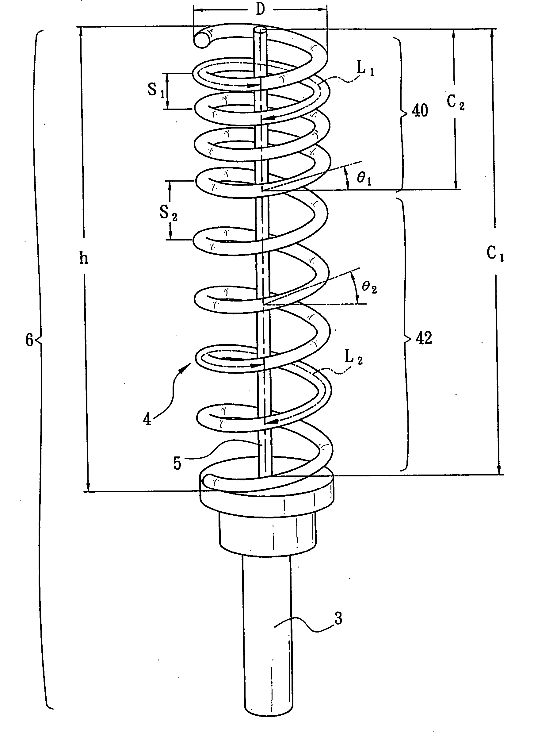
[0018] Referring to FIG. 3, there is shown a multi-mode antenna and multi-band antenna combination (i.e., combination antenna) 6 according to a preferred embodiment of the invention. It comprises a cylindrical conductive seat 3 and a non-uniform helical antenna 4 extending from one end of the conductive seat 3. The helical antenna 4 comprises a first coil section 40 and a second coil section 42 having physical parameters including spiral angle, coil diameter, length, turns, and pitch all different from that of the first coil section 40. Thus, it is possible of tuning the first coil section 40 to a plurality of resonant frequencies different from that to which the second coil section 42 is tuned. A pole antenna 5 is extending from one end of the conductive seat 3 through a central axis of the helical antenna 4. It is possible of adjusting physical parameters including diameter and length of the pole antenna 5 for tuning the pole antenna 5 to a plurality of resonant frequencies differ...


PUM


Abstract

The present invention is to provide a combination antenna having multi-mode and multi-band arrangements, which comprises a conductive seat; a non-uniform helical antenna extending from one end of the conductive seat; and a pole antenna extending from one end of the conductive seat through the helical antenna, enabling to be tuned to three or more resonant frequencies through tuning the helical antenna to a plurality of resonant frequencies and tuning the pole antenna to a plurality of resonant frequencies different from that to which the helical antenna is tuned.

Description

FIELD OF THE INVENTION [0001] The present invention relates to multi-band antennas, more particularly to a multi-mode antenna and multi-band antenna combination by disposing a helical antenna and a pole antenna on a conductive seat, enabling the combination antenna to be tuned to three or more resonant frequencies. BACKGROUND OF THE INVENTION [0002] A wide variety of portable communication products (e.g., cellular phones, PDAs (personal digital assistants), Internet phones, etc.) are commercially available in an even faster pace in recent years as electronics industry advances. Moreover, such portable communication products are provided with many advanced features. Each group of the portable communication products is able to operate in predetermined frequencies due to its specific functions and wireless communication system involved. Currently, dominant wireless communication systems are GSM (Global System for Mobile Communications) (i.e., so-called Pan-European digital mobile phone...

Claims


Application Information

Patent Timeline
IPC IPC(8): H01Q1/36H01Q5/15
CPCH01Q1/362H01Q9/30H01Q5/40H01Q5/371H01Q5/357
Inventor HO, DAVIDGU, DIANHUNG, CHIH-CHUNG
Owner INVENTEC APPLIANCES CORP
Why Eureka
Try Eureka