Check patentability & draft patents in minutes with Patsnap Eureka AI!

Method of preventing charging, and apparatus for charged particle beam using the same

a technology of charged particle beam and charging method, which is applied in the direction of semiconductor/solid-state device testing/measurement, instruments, and therapy, etc., can solve the problems of affecting the observation, analysis and processing, irradiation amount, and operator experience, etc., to achieve excellent analysis and sample fabrication efficiency, preventing charging, and reliable

Inactive Publication Date: 2006-03-23
HITACHI LTD
View PDF10 Cites 0 Cited by
  • Summary
  • Abstract
  • Description
  • Claims
  • Application Information

AI Technical Summary

Benefits of technology

[0018] The present invention has been achieved in consideration of the above and its object is to provide a very reliable method of preventing charging without requiring experience or skills to suppress charging in the surface of a sample and to provide an apparatus for a charged particle beam having generally excellent analysis and sample fabricating efficiency.
[0019] The present invention provides, as means achieving the object, a technique based on novel finding such that charging which occurs when a sample is irradiated with a charged particle beam (ion beam, electron beam, or the like) is controlled by an electrode for preventing charging provided adjacent to or in contact with the irradiated area.
[0020] Even when the electrode for preventing charging and the irradiated area are electrically insulated from each other, when the area is irradiated with a charged particle beam, a current induction occurs between the charged irradiated area and the electrode for preventing charging for the following reason. By efficiently extracting secondary particles emitted from the surface of the sample charged by the irradiation of the charged particle beam by the electrode for preventing charging, a current induction occurs between the electrode for preventing charging and the irradiated area. When the electrode for preventing charging is provided within, for example, 300 μm from the irradiated area or in contact with the irradiated area, by the irradiation of the charged particle beam, a current flows between the charged irradiated area and the electrode for preventing charging.
[0021] When the operator performs observation, analysis, processing, and probe operation of high precision, the interval between the electrode for preventing charging and the irradiated area has to be further reduced. As the interval is reduced, the charging voltage decreases by the induced current or the generated current between the electrode and the irradiated area, and an electric field near the irradiated area generated by the charging can be confined in a narrower space. As a result, the irradiation position of the charged particle beam in the surface of the insulating sample can be controlled with position precision of about 1 / 50 times of the interval. Simultaneously, a secondary particle detection amount in a secondary particle detector is not influenced by charging, so that a clear observation image can be obtained.
[0023] First, the invention provides a method of preventing charging, including the steps of irradiating a sample mounted on a sample holder with a charged particle beam emitted from a charged particle beam source, and applying a predetermined voltage to an electrode for preventing charging disposed near a surface of the sample holder to generate an induced current between the electrode for preventing charging and an irradiated area in which charging occurs in the sample, thereby executing a control of preventing the charging without contact with the sample.

Problems solved by technology

The charging disturbs observation, analysis, and processing due to drift of an emitted beam and decrease in a discharge amount of secondary particles.
Further, control of the irradiation amount by the charging preventing condition detecting means requires experience of the operator.
When a charging amount of the surface of a sample is large, the charging preventing method by irradiation of an electron or ion beam is not effective.
However, in the case of emitting an electron or ion beam in order to prevent charging, due to generation of secondary electrons, the resolution of an observation image based on the secondary electron signals deteriorates more than that of an observation image based on secondary ions.
When the surface of a sample is covered, however, the structure of the surface cannot be observed with a charged particle beam, and a problem occurs in determination of a position of observation, analysis, and processing with a charged particle beam.
By making the terminal come into contact with the periphery of at least 180 degrees of the region of observation, analysis, and processing, it becomes difficult to recognize the contact of the terminal and, simultaneously, positioning precision in the state where the terminal is in contact deteriorates.
Further, a region wider than the observation, analysis, and processing region irradiated with the charged particle beam is contaminated by the contact of the terminal.
When the operator fails in the processing, the sample may be destroyed.
When the operator fails in a probe operation, the sample or the tip of the probe may be destroyed.

Method used


Image

  • Method of preventing charging, and apparatus for charged particle beam using the same
  • Method of preventing charging, and apparatus for charged particle beam using the same
  • Method of preventing charging, and apparatus for charged particle beam using the same

Examples


first embodiment

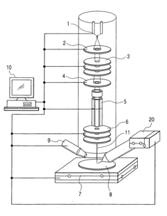
[0044]FIG. 1 shows a basic configuration of a first embodiment of an apparatus for a charged particle beam according to the invention.

[0045] The apparatus for a charged particle beam of the invention includes a charged particle optical system for extracting an ion beam 11 by an electrode 2 from an ion source 1, condensing the ion beam 11 by a condenser lens 3, narrowing the ion beam 11 by an aperture 4, and focusing the ion beam 11 onto the surface of a sample 8 by an objective lens 6, a movable sample holder 7 on which a sample is mounted, a secondary particle detector 9, a deflector 5, a controller 10, and an electrode 20 for preventing charging.

[0046] The electrode 20 for preventing charging takes the form of an electrode made of a conductive material. The tip portion of the electrode 20 for preventing charging approaches an ion beam irradiation position of the sample 8 by in-plane position measuring means for making observation by scanning with an ion beam and height position ...

second embodiment

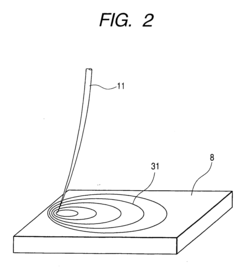
[0060]FIG. 9 shows a basic configuration of a second embodiment of an apparatus for a charged particle beam according to the invention. In the embodiment, by assembling a probe manipulator 21, an apparatus for a charged particle beam for fabricating a sample of the order of a few μm to a sub μm is constructed.

[0061] The apparatus for a charged particle beam of the second embodiment includes the charged particle optical system for extracting the ion beam by the extraction electrode 2 from the ion source 1, condensing the ion beam 11 by the condenser lens 3, narrowing the ion beam 11 by the aperture 4, and focusing the ion beam 11 onto the surface of the sample 8 by the objective lens 6, the movable sample holder 7 on which a sample is mounted, the secondary particle detector 9, the deflector 5, the controller 10, the electrode 20 for preventing charging, and the probe manipulator 21.

[0062] The tip portion of the electrode 20 for preventing charging takes the form of a conductive ne...

third embodiment

[0068]FIG. 11 shows a basic configuration of a third embodiment of an apparatus for a charged particle beam of the invention.

[0069] The apparatus for a charged particle beam of the invention includes a charged particle optical system for extracting an electron beam 82 by an extraction electrode 81 from an electron source 80, condensing the electron beam 82 by a condenser lens 83, and focusing the electron beam 82 onto the surface of a sample 85 by an objective lens 84, a movable sample holder 86 on which the sample 85 is mounted, a secondary electron detector 87, a deflector 88, a controller 89, and an electrode 90 for preventing charging.

[0070] If the sample 85 contains an insulating material, an area irradiated with the electron beam 82 may be charged. Most of secondary electrons emitted from the surface of a sample by the irradiation of the electron beam 82 have an energy of only a few eV. When the secondary electrons are positively charged, they cannot be liberated from the sa...


PUM

PropertyMeasurementUnit
voltageaaaaaaaaaa
dielectric constantaaaaaaaaaa
insulation resistanceaaaaaaaaaa

Abstract

An apparatus for a charged particle beam has a charged particle source; a charged particle optical system for focusing and deflecting a charged particle beam emitted from the charged particle source; a detector for detecting secondary particles emitted from a sample irradiated with the charged particle beam; and a sample holder on which the sample is mounted. The apparatus has an electrode for preventing charging which is provided so as to be movable with respect to the surface of the sample holder, and a controller for the electrode for preventing charging, which controls a voltage to be applied to the electrode for preventing charging and the movement. Preventing the charging is performed by generating an induced current or a current between an area irradiated with the charged particle beam in the sample and the electrode for preventing charging.

Description

BACKGROUND OF THE INVENTION [0001] The present invention relates to a charged particle beam technique for irradiating a sample with a charged particle beam, to observe, analyze, and process the sample. [0002] An apparatus for a charged particle beam for irradiating a sample with a charged particle beam and observing, analyzing, and processing the sample is widely used. In the case where a sample contains an insulating material, when the surface of the sample is scanned with a charged particle beam, the surface of the sample may be charged. The charging disturbs observation, analysis, and processing due to drift of an emitted beam and decrease in a discharge amount of secondary particles. Consequently, a method of preventing the charging is important. [0003] Conventional charging preventing methods include a method of preventing charging by irradiating the surface of a sample with a charged particle beam, a method of making charges escape by forming a conductive layer on the surface ...

Claims


Application Information

Patent Timeline
Patent Type & Authority Applications(United States)
IPC IPC(8): A61N5/00G01N23/225G01Q10/00G01Q30/02G01Q30/20H01J37/02H01J37/20H01J37/28H01J37/305H01L21/66
CPCG01N23/225H01J37/3056H01J37/28H01J37/026
Inventor FUKUDA, MUNEYUKISHICHI, HIROYASUTOMIMATSU, SATOSHI
Owner HITACHI LTD
Features
  • R&D
  • Intellectual Property
  • Life Sciences
  • Materials
  • Tech Scout
  • Unparalleled Data Quality
  • Higher Quality Content
  • 60% Fewer Hallucinations
Learn More