Oil filter assembly

a technology of oil filter and assembly, which is applied in the direction of filtration separation, lubricant mounting/connection, separation process, etc., can solve the problems of reducing the filtering ability, requiring the replacement of the entire filter assembly, and prone to sticking of threaded interfaces

a technology of oil filter and assembly, which is applied in the direction of filtration separation, lubricant mounting/connection, separation process, etc., can solve the problems of reducing the filtering ability, requiring the replacement of the entire filter assembly, and prone to sticking of threaded interfaces

US20060096934A1Inactive Publication Date: 2006-05-11WEINBERGER KEITH R +10

Image

  • Oil filter assembly
  • Oil filter assembly
  • Oil filter assembly

Examples


Embodiment Construction

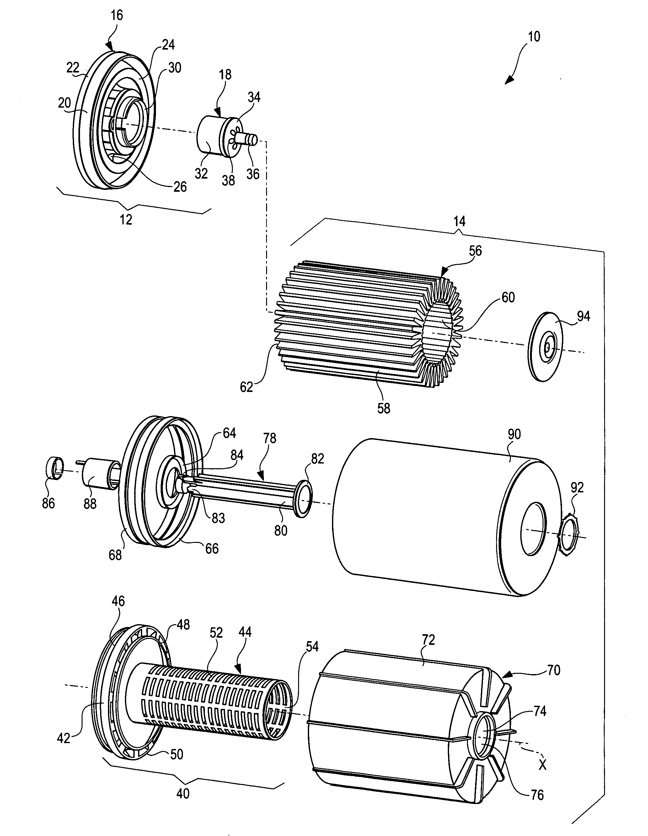
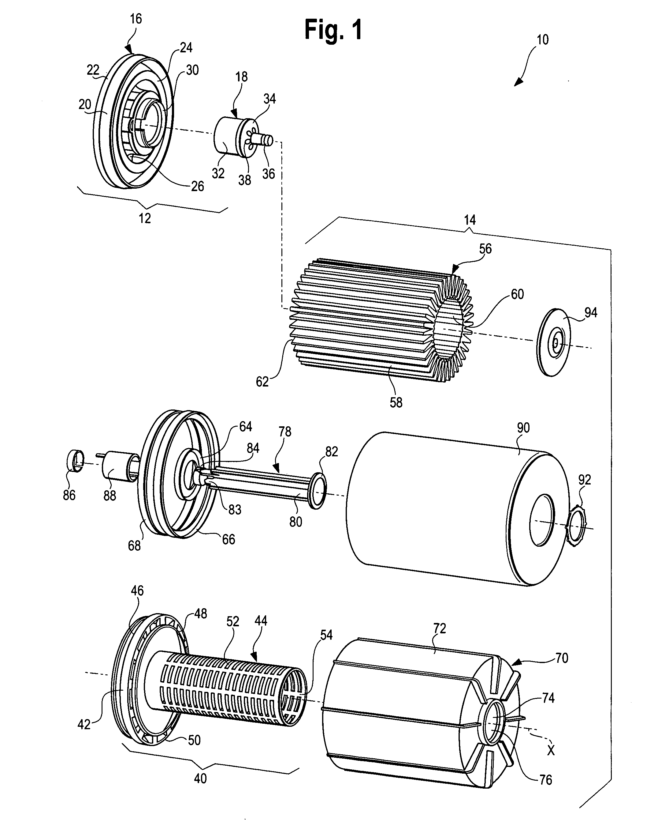
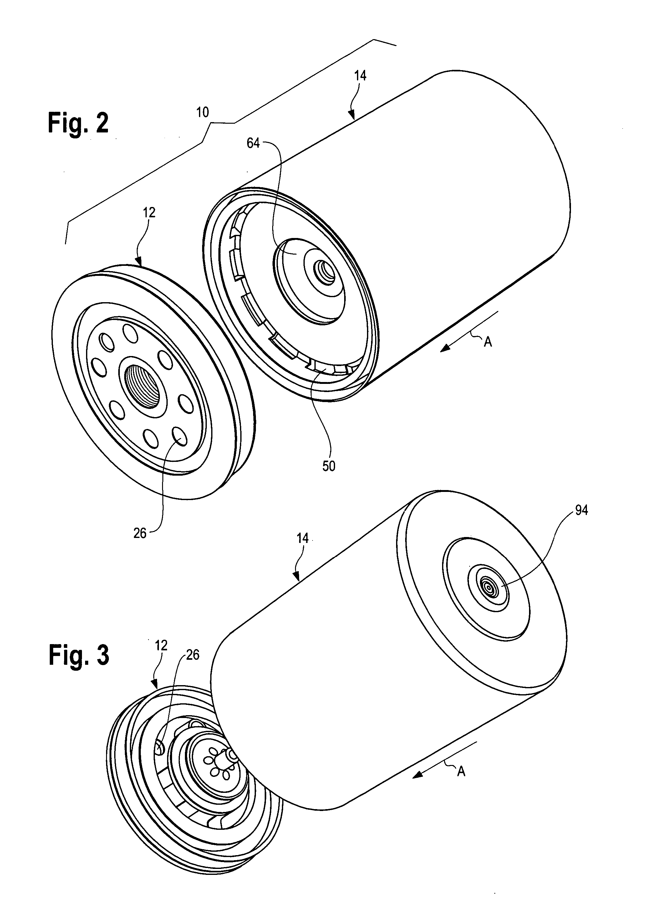
[0060]FIG. 1 illustrates an isometric exploded view of an oil filter assembly 10 according to an embodiment of the present invention. The oil filter assembly 10 includes a first segment, such as an adapter 12 and a second segment, such as a filter module 14, or insert. The adapter 12, which may be a metal, such as steel, an aluminum silicon alloy, or a nonmetallic material, includes a generally circular adapter base 16 and an insert securing member 18. The base 16 includes an outer wall 20 integrally formed with an engine engagement surface 22, and an insert engagement surface 24. A plurality of oil inlet openings 26 are formed between and through the engine engagement surface 22 and the insert engagement surface 24. The interior portion of the engine engagement surface 22 may be threaded and adapted to threadably engage a mounting structure (not shown) of an engine (not shown) in a conventional manner. Thus, the base 16 may be threadably secured, such as through rotating or screwin...


PUM

PropertyMeasurementUnit
angleaaaaaaaaaa
forceaaaaaaaaaa
rotationaaaaaaaaaa

Abstract

An oil filter system includes an oil filter module and an adapter. The oil filter module includes a detent and an actuator. The adapter includes a protuberance and is configured to be secured to the engine. The oil filter module connects to the adapter when the detent secures to the protuberance as the oil filter module is urged into a connection position with the adapter. The oil filter module disconnects from the adapter when the actuator is actuated, thereby disengaging the detent from the protuberance.

Description

RELATED APPLICATIONS [0001] This application relates to and claims priority benefits of U.S. Provisional Application No. 60 / 625,522, entitled “Oil Filter Assembly,” which was filed Nov. 5, 2004, which is hereby incorporated by reference in its entirety.BACKGROUND OF THE INVENTION [0002] Embodiments of the present invention generally relate to an oil filter assembly, and more particularly to an oil filter assembly that is configured to be quickly and easily changed. [0003] A conventional oil filter assembly for an internal combustion engine typically includes a threaded end, which is rotated, twisted, or spun, onto a corresponding mounting structure of the engine. Once the assembly is mounted onto the engine, oil is circulated through the engine for filtering. Unfiltered oil from the engine is passed through a filtering media, such as a pleated paper cylinder, of the assembly. As the unfiltered oil passes through the filtering media, impurities contained within the oil are retained b...

Claims


Application Information

Patent Timeline
11 May 2006
Publication
US20060096934A1
IPC
B01D35/00
CPC
B01D29/21; B01D35/147; B01D2201/291; B01D2201/304; B01D2201/305; B01D2201/34; B01D2201/4023; F01M11/03
Inventors
WEINBERGER, KEITH R.; JOHNSON, ALAN