Pre-chilling heat sink driving device

Inactive Publication Date: 2006-07-06
ZIPPY TECH
View PDF10 Cites 0 Cited by
  • Summary
  • Abstract
  • Description
  • Claims
  • Application Information

AI Technical Summary

Benefits of technology

[0003] Therefore, the primary objective of the present invention is to solve the foregoing problems and avoid the existing deficiencies by adopting a suppression measure to detect a parameter source that will affect the heat source to produce a temperature rise and use such parameter source as the parameter source for controlling the rotary speed of a heat sink instead of the traditional way of controlling the rotary speed of a heat sink by increasing the temperature and then lowering the temperature of a heat source of an electronic device. Thus, the electronic device and its heat source in accordance with the present invention achieve the effects of suppressing a temperature rise and operating normally in a specific temperature range.

Problems solved by technology

However, the demand for high performance continues and the issue of heat dissipation for the electronic device 10 becomes more serious than ever.
However, such arrangement no longer can meet the requirements of an electronic device 10.
Since the high power output conditions of the electronic device 10 remains unchanged, the heat sink 60 can only suppress the temperature of the heat source operated under a high power output condition, but cannot really achieve the objective of effectively lowering the temperature.

Method used


Image

  • Pre-chilling heat sink driving device
  • Pre-chilling heat sink driving device
  • Pre-chilling heat sink driving device

Examples


Embodiment Construction

[0009] The above and other objects, features, and advantages of the present invention will become apparent from the following detailed description taken with the accompanying drawing.

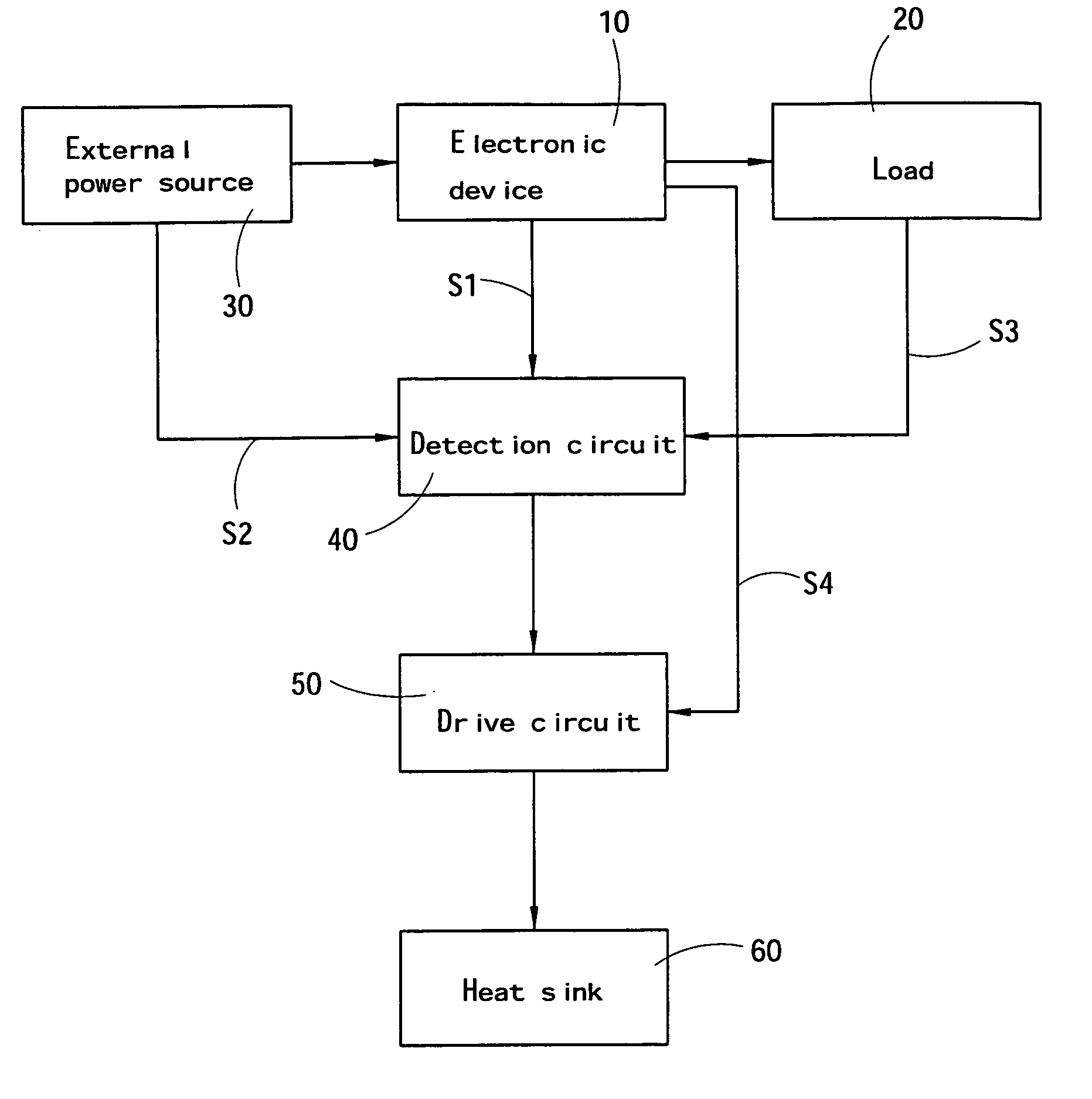
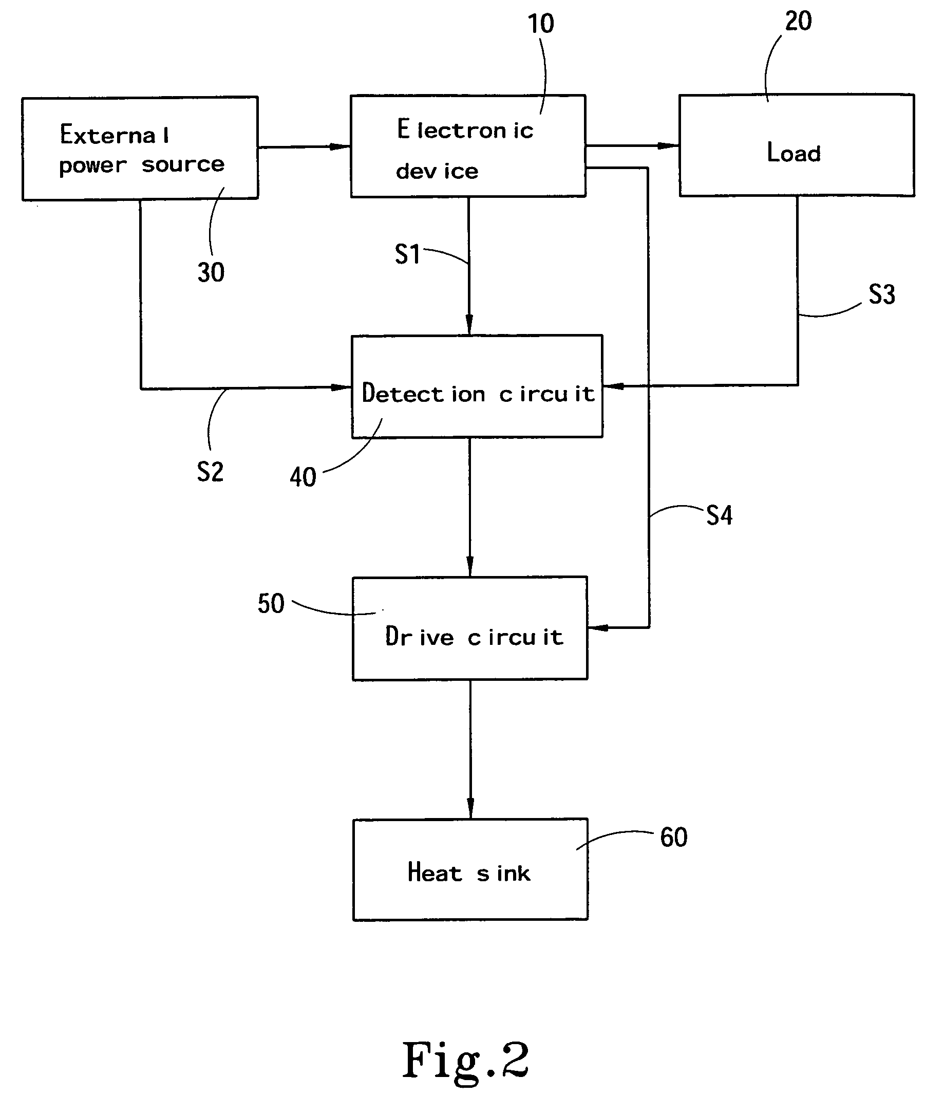
[0010] Please refer to FIG. 2 for the present invention, which is applied to an electronic device 10 having a heat source and a pair of heat sinks 60 for lowering the temperature of the heat source, and the electronic device 10 installs a drive circuit 50 for controlling the performance of lowering the temperature of the heat sink 60, wherein the drive circuit 50 is connected to a detection circuit 40, and the detection circuit 40 obtains a detective signal from a parameter source that affects the heat source to produce a temperature rise, and based on the detective signal, the detection circuit 40 outputs an acceleration signal or a deceleration signal to the drive circuit 50 to control the heat sink 60 for pre-chilling or lowering the temperature of the heat source in advance.

[0011] Please refer to ...


PUM


Abstract

A pre-chilling heat sink driving device mainly improves the existing heat sink that simply uses the temperature change of a heat source of an electronic device as a parameter source to determine its rotary speed, and the present invention uses a parameter source that will affect the heat source to produce a temperature rise as the parameter source for accelerating the rotation of the heat sink if a temperature rise to the heat source of the electronic device is expected, and thus the invention normally maintains the heat source at a normal operating temperature to assure the operational performance.

Description

FIELD OF THE INVENTION [0001] The present invention relates to a pre-chilling heat sink driving device and its control method, more particularly to a pre-chilling heat sink driving device that timely controls the rotary speed of a heat sink and effectively lowers the temperature of an electronic device. BACKGROUND OF THE INVENTION [0002] Since the precision technology is well developed, the electronic device 10 is getting smaller day after day. However, the demand for high performance continues and the issue of heat dissipation for the electronic device 10 becomes more serious than ever. With reference to FIG. 1, most temperature sensing heat sinks 60 disclosed in the patented technologies and products adopt a design of using a temperature detection circuit 40a of a thermistor or any temperature sensitive component to continuously detect the temperature change of a heat source of the electronic device 10 during its operation. If the temperature of a hot source detected by the temper...

Claims


Application Information

Patent Timeline
IPC IPC(8): F25B9/00F25D17/00F25D23/12
CPCG06F1/206H05K7/20209
Inventor MO, HSIEN-PENG
Owner ZIPPY TECH
Why Eureka
Try Eureka