Lighting unit for motor vehicles

Inactive Publication Date: 2006-09-07
HELLA KGAA HUECK & CO
View PDF9 Cites 11 Cited by
  • Summary
  • Abstract
  • Description
  • Claims
  • Application Information

AI Technical Summary

Benefits of technology

[0009] The particular advantage of the invention lies in that, due to the concentrated arrangement of the semiconductor light sources on a common carrier substrate and the associated high packing density of semiconductor light sources, the luminance of the light source can be substantially increased. For ease of manufacture, the individual semiconductor light sources can be arranged as chips on a common carrier substrate. A common chip cover which is transparent to light and a light-scattering and/or light-converting auxiliary medium integrated therein cause a homogeneously illuminating light exit surface. A spatially concentrated light source with a relatively high luminance is advantageous according to the invention. A shading device causes a relatively steep transition of light intensity in the boundary region between a first grid segment activated by a control unit and a second grid segment not activated by the control unit. As a result, a relatively sharp light/dark boundary can be achieved. The grid segments can, for example, be activated to form a dipped beam and a main beam.
[0010] According to a development of the invention, the shading device is designed as a partition arranged between the first grid segment and the second grid segment, the free end of the partition being spaced apart from a front side of the chip cover in such a way that there is a minor light interaction between the adjacent grid segments

Problems solved by technology

A disadvantage of the known lighting unit is that the grids or grid segments have a relati

Method used


Image

  • Lighting unit for motor vehicles
  • Lighting unit for motor vehicles
  • Lighting unit for motor vehicles

Examples


Embodiment Construction

[0020] The following description of the preferred embodiment(s) is merely exemplary in nature and is in no way intended to limit the invention, its application, or uses.

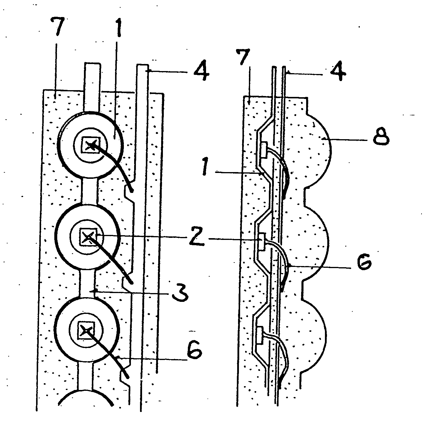
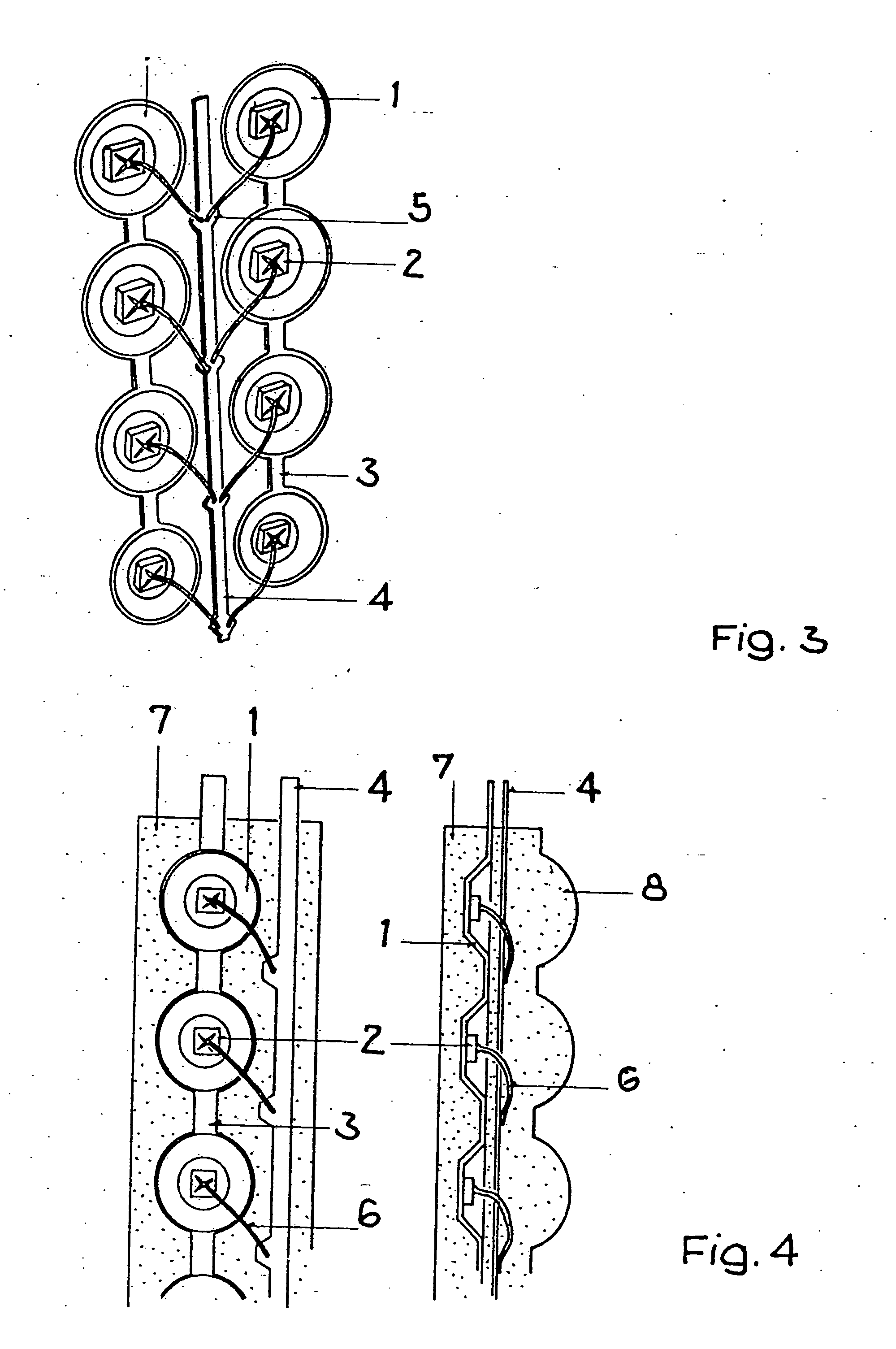
[0021] A lighting unit for vehicles, in particular motor vehicles, essentially consists of a light source 1 and an optical element 2 which projects the light beam emitted from the light source 1 directly according to a predetermined light distribution.

[0022] The lighting unit according to the invention can serve, for example, as a headlamp for the generation of a dipped beam, main beam, motorway beam and / or cornering beam function.

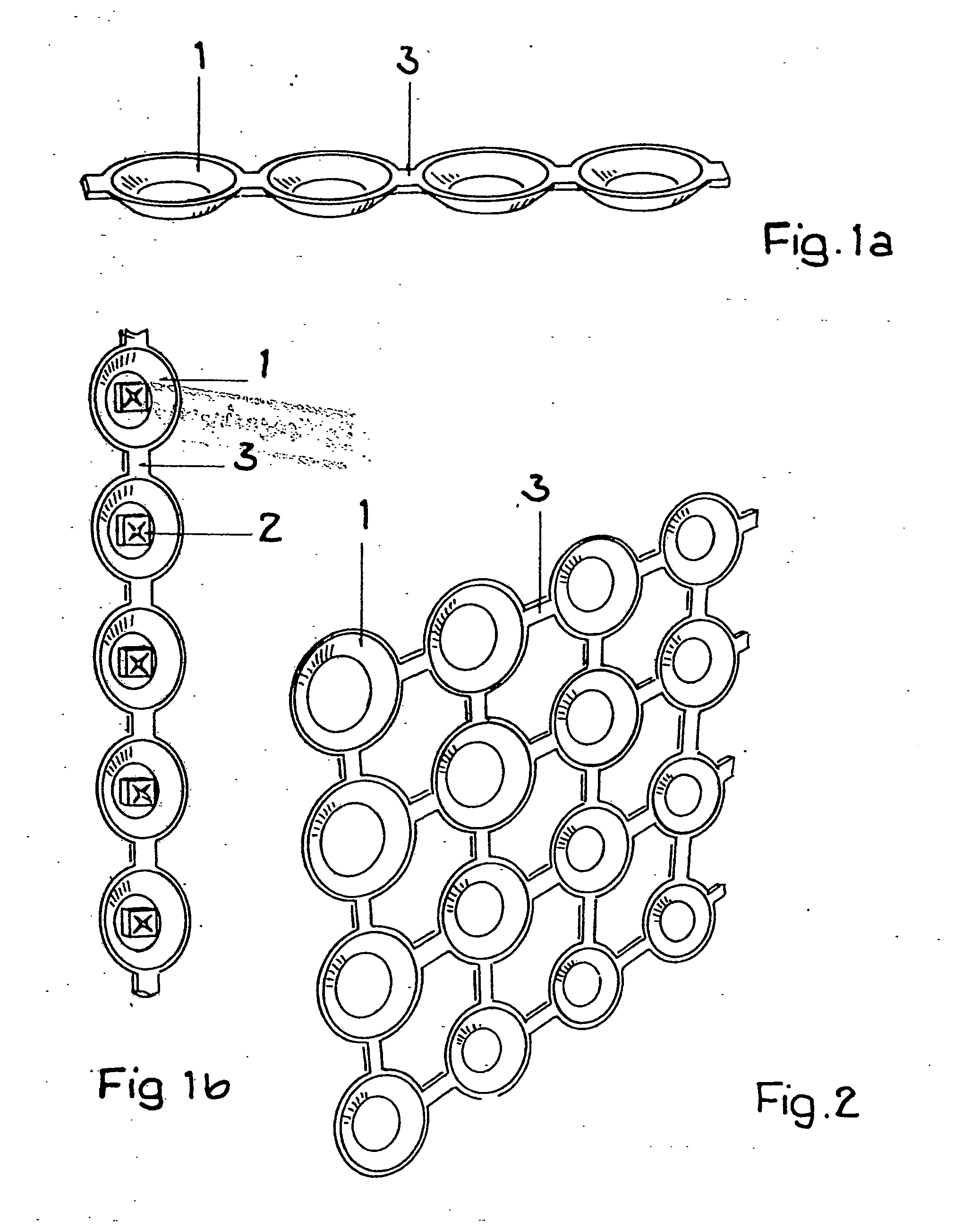
[0023] The light source 1 is formed from a plurality of semiconductor light sources 3, in particular LED light sources (light-emitting diodes), which are arranged after the fashion of a grid 4 on a common carrier substrate 5.

[0024] As can be seen from FIG. 2, the semiconductor light sources 3 are arranged regularly adjacent to and under each other. The semiconductor light sources 3 are ...


PUM


Abstract

A lighting unit for vehicles has a plurality of semiconductor light sources distributed in a grid. The grid of semiconductor light sources is divided into at least two grid segments, the grid segments being each activatable independently of each other and/or assigned to a different light functions, with an optical element in the beam path of a light beam emitted by the semiconductor light sources. The semiconductor light sources (3) are arranged on a common carrier substrate (5), with a chip cover (6) transparent to light in the direction of light propagation, in that the chip cover (6) is filled with a light-scattering and/or light-converting auxiliary material (8) and in that a shading device (9) is provided such that, in the boundary region between the activated grid segment (10) and the unactivated grid segment (11), a relatively steep transition of light intensity is adjustable to form a light/dark boundary.

Description

CROSS-REFERENCE TO RELATED APPLICATIONS [0001] This application is a National Stage application of International Application No. WO 2004 / 088202 PCT / EP2004 / 003566 filed on Apr. 3, 2004 and claims priority to German Application No. 103 15 133.8 filed on Apr. 3, 2003.BACKGROUND OF THE INVENTION [0002] 1. Field of the Invention [0003] The invention concerns a lighting unit for vehicles with a plurality of semiconductor light sources distributed in a grid, the grid of semiconductor light sources being divided into at least two grid segments, the grid segments being each activatable independently of each other and / or assigned to a different light function, with an optical element in the beam path of a light beam emitted by the semiconductor light sources [0004] 2. Related Art [0005] From DE 100 09 782 A1 is known a lighting unit for motor vehicles, which has as a light source a plurality of semiconductor light sources arranged in a grid. The grid of semiconductor light sources is divided ...

Claims


Application Information

Patent Timeline
IPC IPC(8): F21V9/16F21V5/04B60Q1/14F21S8/10F21V11/16
CPCB60Q1/1415F21S48/1154F21S48/145F21S48/1747F21Y2101/02F21S41/143F21S41/153F21S41/43F21S41/663F21Y2115/10
Inventor EICHHORN, KARSTENHAGEDORN, SUSANNE
Owner HELLA KGAA HUECK & CO
Why Eureka
Try Eureka