Cathode ray tube and image display apparatus using the same
a cathode ray tube and image display technology, applied in cathode ray tubes/electron beam tubes, electrical devices, electric discharge tubes, etc., can solve the problems of inapplicability, inability to use, and insufficient vibration restriction effect of elastic support 2001, so as to eliminate electron beam mislanding, and quickly attenuate frame vibration
- Summary
- Abstract
- Description
- Claims
- Application Information
AI Technical Summary
Benefits of technology
Problems solved by technology
Method used
Image

Examples
example 1
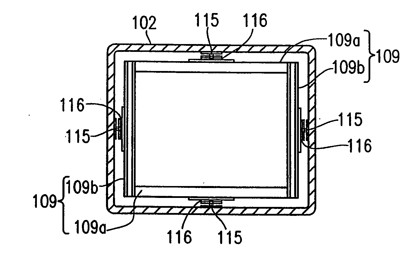
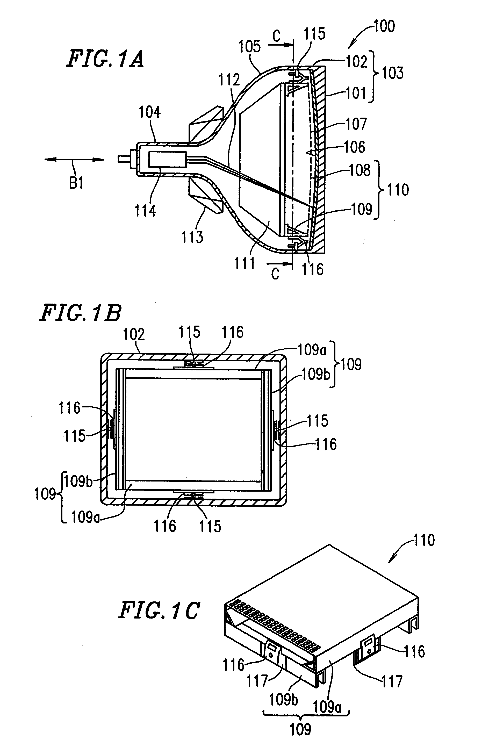
[0153]FIG. 1A shows a cathode ray tube 100 in Example 1 according to the present invention. FIG. 1B is a cross-sectional view of the cathode ray tube 100 shown in FIG. 1A taken along lines C-C in FIG. 1A. The cathode ray tube 100 includes a substantially quadrangular panel 103 having an effective display section 101 and a side wall 102 provided around four sides thereof, and a funnel 105 including a neck 104.
[0154] On an inner surface of the effective display section 101 of the panel 103, a phosphor screen 106 is provided. The phosphor screen 106 includes three color phosphor elements respectively providing red (R), green (G) and blue (B) light, which are arranged two-dimensionally. A mask frame 110 is engaged with the panel 103 so as to face the phosphor screen 106 by a mask frame supporting device described later. The mask frame 110 includes a frame 109 and a substantially quadrangular mask 108 attached to the frame 109. The mask 108 has a gradual curved surface, which has a plur...
example 2
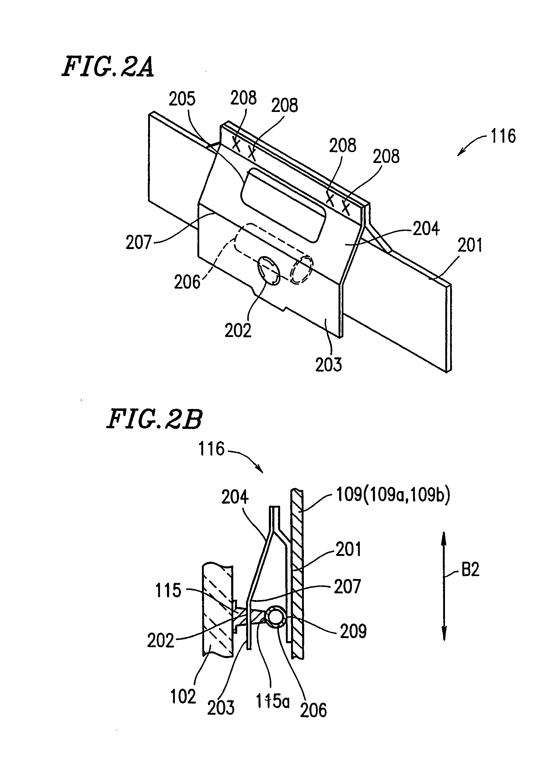
[0169] In Example 2 according to the present invention, a cathode ray tube having the structure shown in FIGS. 1A through 1C includes elastic supports 116A shown in. FIGS. 3A and 3B instead of the elastic supports 116 shown in FIGS. 2A and 2B. Identical elements previously discussed with respect to FIGS. 2A and 2B bear identical reference numerals and the descriptions thereof will be omitted. The description below will be done regarding one elastic support 116A for convenience unless specified otherwise.
[0170] The elastic support 116A includes an elastic portion 301 having a different structure from that of the elastic portion 206. The elastic portion 301 is a metal plate bent into a leaf spring shape. One of two ends of the elastic portion 301 is fixed to the fixing portion 201 by welding. As in the structure shown in FIGS. 2A and 2B, when the stud pin 115 is inserted through the engaging hole 202, the tip 115a of the stud pin 115 is constantly in contact with the elastic portion ...
example 3
[0173] In Example 3 according to the present invention, a cathode ray tube having the structure shown in FIGS. 1A through 1C includes elastic supports 116B shown in FIGS. 4A and 4B instead of the elastic supports 116 shown in FIGS. 2A and 2B. Identical elements previously discussed with respect to FIGS. 2A and 2B bear identical reference numerals and the descriptions thereof will be omitted. The description below will be done regarding one elastic support 116B for convenience unless specified otherwise.
[0174] The elastic support 116B includes an elastic portion 401 having a different structure from that of the elastic portion 206. The elastic portion 401 includes two metal plates each rolled into a cylindrical shape. The two metal plates in the cylindrical shape are fixed to the fixing portion 201 by welding so as to have the engaging hole 202 interposed. When the stud pin (not shown) is inserted through the engaging hole 202, an outer surface 402 of each elastic portion 401 and an...
PUM
 Abstract
Description
Claims
Application Information
 - R&D
- Intellectual Property
- Life Sciences
- Materials
- Tech Scout
- Unparalleled Data Quality
- Higher Quality Content
- 60% Fewer Hallucinations
Browse by: Latest US Patents, China's latest patents, Technical Efficacy Thesaurus, Application Domain, Technology Topic, Popular Technical Reports.
© 2025 PatSnap. All rights reserved.Legal|Privacy policy|Modern Slavery Act Transparency Statement|Sitemap|About US| Contact US: help@patsnap.com