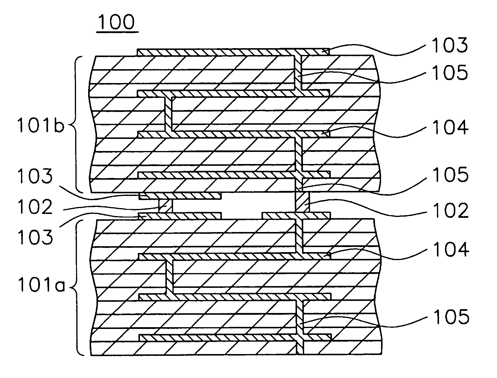
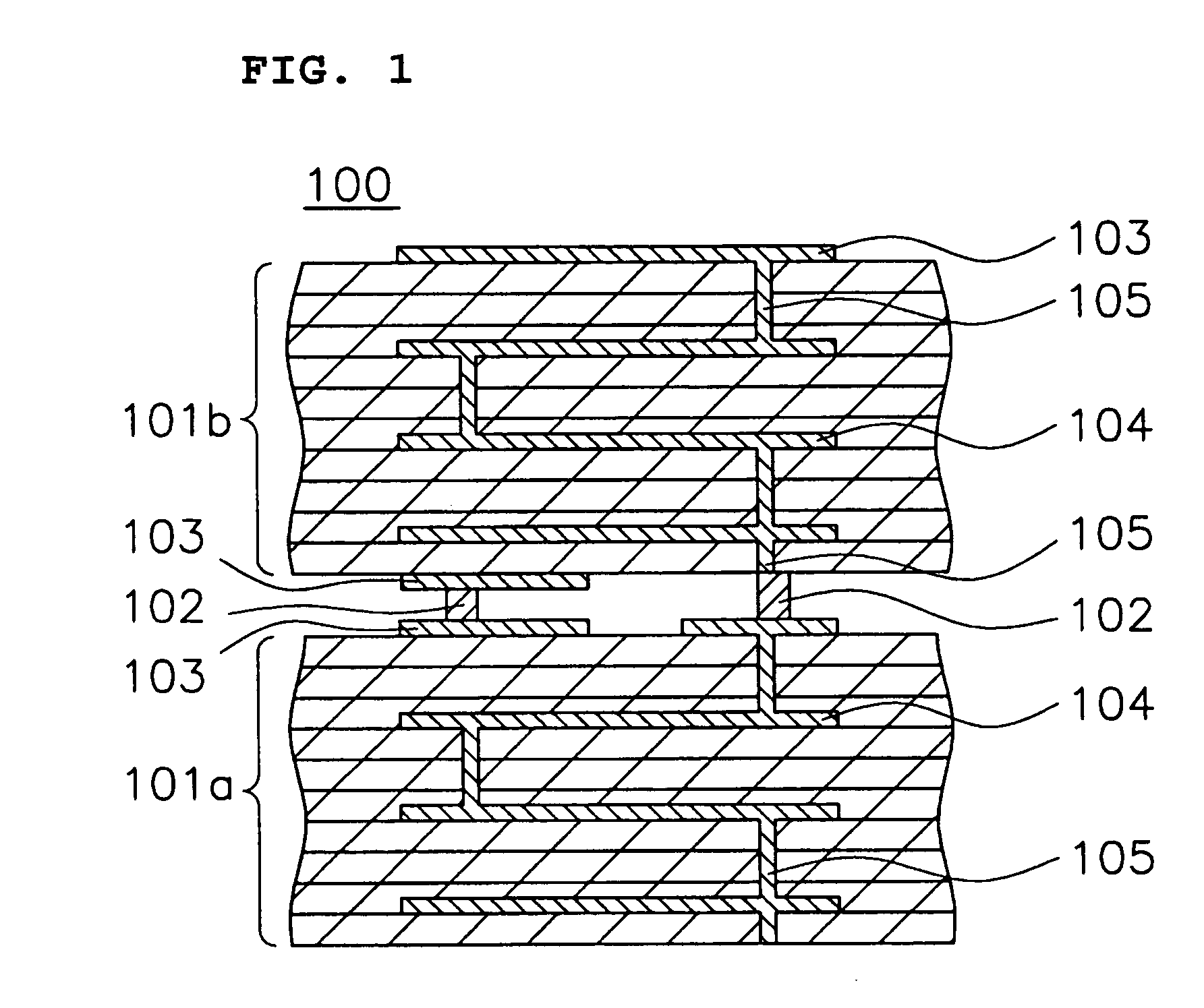
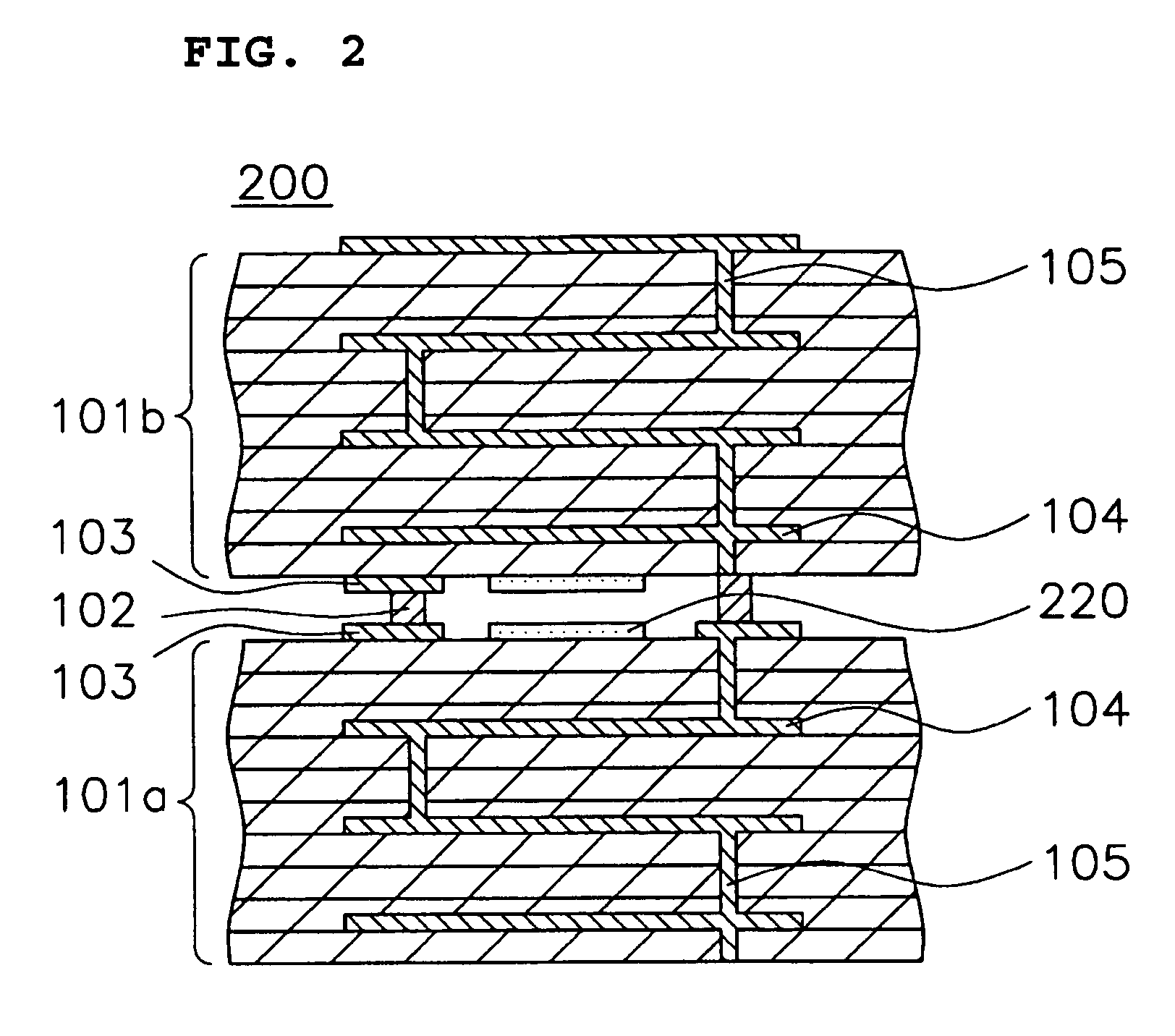
Ceramic structure, method for manufacturing ceramic structure, and nonreciprocal circuit device
a ceramic structure and ceramic technology, applied in the direction of fixed capacitor details, stacked capacitors, fixed capacitors, etc., can solve the problems of difficult to form conductive bumps, difficult to control the shape of metal balls after melting, and metal ball displacement in some cases
- Summary
- Abstract
- Description
- Claims
- Application Information
AI Technical Summary
Benefits of technology
Problems solved by technology
Method used
Image

Examples
example 1
[0123] Hereinafter, one example of a manufacturing method of a ceramic multilayer substrate of various preferred embodiments of the present invention will be described.
[0124] First, to 100 parts by weight of a powdered mixture composed of a powdered CaO—Al2O3-SiO2-based glass and powdered Al2O3 in an amount equivalent thereto on a weight basis, 15 parts by weight of polyvinyl butyral, 40 parts by weight of isopropyl alcohol, and 20 parts by weight of toluene were respectively added and were then mixed for 24 hours by a ball mill to form a slurry, followed by defoaming the slurry. Subsequently, using a doctor blade method, substrate-forming ceramic green sheets having a thickness of 100 μm were formed.
[0125] Next, to 100 parts by weight of powdered Al2O3, 15 parts by weight of polyvinyl butyral, 40 parts by weight of isopropyl alcohol, 20 parts by weight of toluene, and 1 part by weight of polyoxyethylene nonylphenyl ether were respectively added and were then mixed for 24 hours by...
example 2
[0130] Hereinafter, one example of a manufacturing method of a ceramic multilayer substrate of various preferred embodiments of the present invention will be described.
[0131] First, to 100 parts by weight of a powdered mixture composed of a powdered MgO—Al2O3-SiO2-based glass and powdered Al2O3 in an amount equivalent thereto on a weight basis, 15 parts by weight of polyvinyl butyral, 40 parts by weight of isopropyl alcohol, and 20 parts by weight of toluene were respectively added and were then mixed for 24 hours by a ball mill to form a slurry, followed by defoaming the slurry. Subsequently, using a doctor blade method, first substrate-forming ceramic green sheets having a thickness of about 100 μm were formed.
[0132] Next, to 100 parts by weight of a powdered mixture composed of a powdered CaO—Al2O3-SiO2-based glass and powdered Al2O3 in an amount equivalent thereto on a weight basis, 15 parts by weight of polyvinyl butyral, 40 parts by weight of isopropyl alcohol, and 20 parts ...
PUM
| Property | Measurement | Unit |
|---|---|---|
| temperature | aaaaa | aaaaa |
| temperature | aaaaa | aaaaa |
| pressure | aaaaa | aaaaa |
Abstract
Description
Claims
Application Information
 - R&D
- Intellectual Property
- Life Sciences
- Materials
- Tech Scout
- Unparalleled Data Quality
- Higher Quality Content
- 60% Fewer Hallucinations
Browse by: Latest US Patents, China's latest patents, Technical Efficacy Thesaurus, Application Domain, Technology Topic, Popular Technical Reports.
© 2025 PatSnap. All rights reserved.Legal|Privacy policy|Modern Slavery Act Transparency Statement|Sitemap|About US| Contact US: help@patsnap.com