
Gasification furnace

Inactive Publication Date: 2007-01-18
EBARA CORP
View PDF2 Cites 11 Cited by
  • Summary
  • Abstract
  • Description
  • Claims
  • Application Information

AI Technical Summary

Benefits of technology

[0006] The present invention has been made in view of the above drawbacks. It is, therefore, a first object of the present invention to provide a gasification furnace which allows a general material to be used for components therein and have a long repair period.
[0007] According to an aspect of the present invention, there is provided a gasification furnace which allows a general material to be used for components therein and have a long repair period. The gasification furnace has a gasification chamber for pyrolyzing a raw material in a fluidized medium being fluidized therein to produce a pyrolysis gas and a pyrolysis residue. The gasification furnace also has a combustion chamber for receiving the pyrolysis residue together with the fluidized medium, combusting the pyrolysis residue in the fluidized medium being fluidized therein to heat the fluidized medium, and returning the fluidized medium to the gasification chamber. The gasification furnace includes a partition wall for separating the gasification chamber and the combustion chamber from each other. The partition wall includes a first steel plate having a cooling structure to prevent the pyrolysis gas from flowing between the gasification chamber and the combustion chamber.
[0009] A combustion gas can be produced in the combustion chamber 2. The partition wall can prevent the combustion gas from flowing between the gasification chamber and the combustion chamber. Thus, the gasification furnace can be a separation-type gasification furnace, which separately produces a combustible gas and a combustion gas.
[0011] As described above, the partition wall has a structure to prevent the pyrolysis gas from flowing between the gasification chamber and the combustion chamber. For example, a gas produced in one of the chambers may be extracted, controlled, and supplied to the other of the chambers. Particularly, it is desirable to extract such a gas at a location other than the partition wall. For example, a gas may be extracted through a path connected to the partition wall and supplied to the other of the chambers. Such an arrangement is included in a partition wall having a structure to prevent the pyrolysis gas from flowing between the gasification chamber and the combustion chamber.
[0012] The gasification chamber and the combustion chamber are configured so that gases are prevented from flowing between the gasification chamber and the combustion chamber. Accordingly, gases in the respective chambers can be separated from each other without being mixed with each other. Since the gasification chamber and the combustion chamber are separated by the partition wall including a first steel plate having the cooling structure, a lifetime of the partition wall can be prolonged.

Problems solved by technology

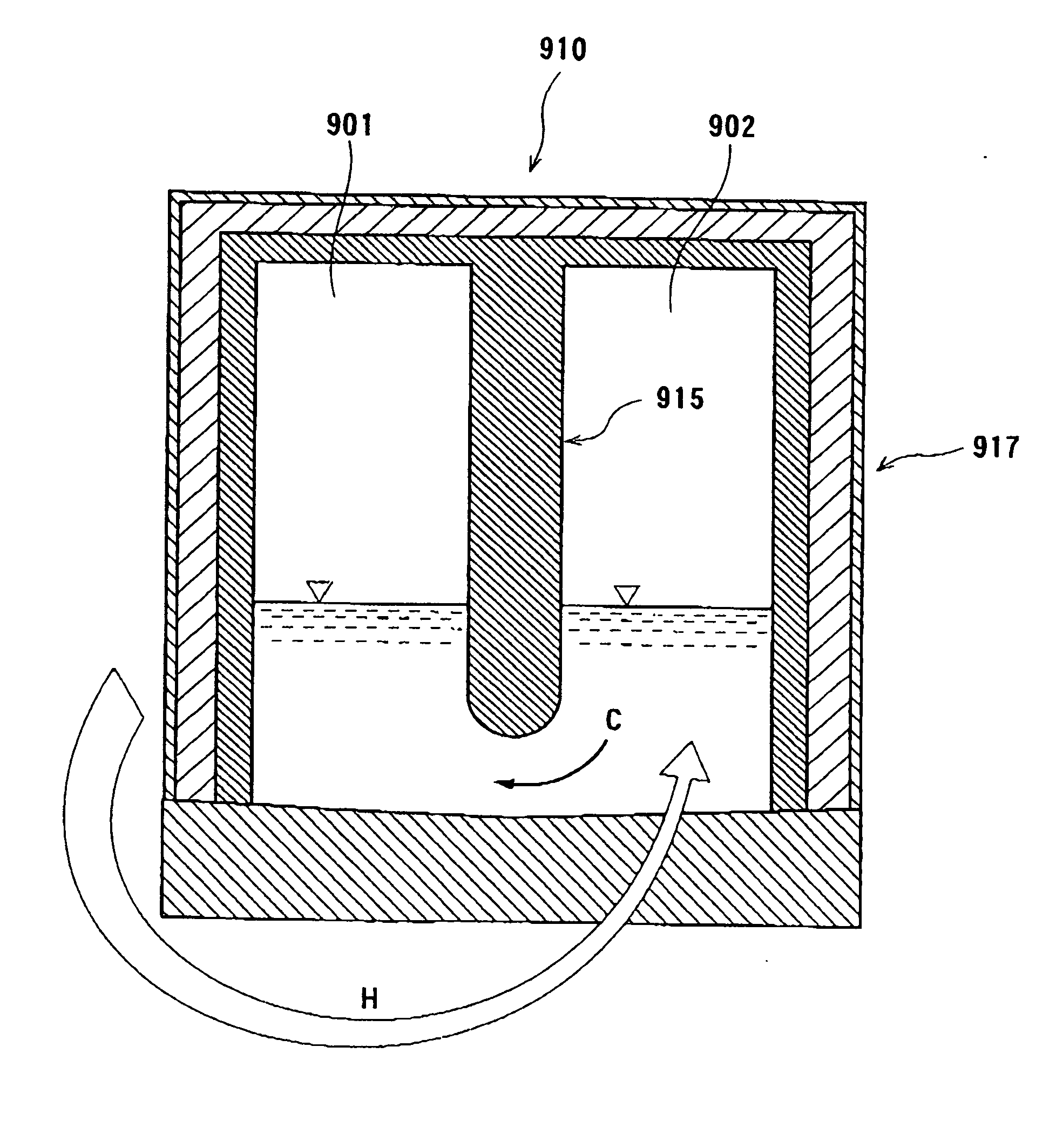
Further, in a case where the partition wall 915 is made of ceramics or brick, the partition wall 915 is likely to be cracked because of its brittleness.

Method used


Image

  • Gasification furnace
  • Gasification furnace
  • Gasification furnace

Examples


first embodiment

[0036]FIG. 2A is a cross-sectional plan view showing an integrated gasification furnace 100 as a fluidized-bed gasification furnace according to the present invention. As shown in FIG. 2A, the integrated gasification furnace 100 has a gasification chamber 1 for pyrolyzing a raw material such as various wastes or solid fuel and a char combustion chamber 2 for combusting char to heat a fluidized medium therein. The gasification chamber 1 and the char combustion chamber 2 are separated from each other by a partition wall 15. Dense beds including a fluidized medium are formed on furnace bottoms of the gasification chamber 1 and the char combustion chamber 2, respectively. The fluidized beds are fluidized by a diffuser (not shown).

[0037] As shown in FIG. 2A, the combustion chamber 2 is separated from the exterior of the furnace by a circumferential furnace wall 17. The circumferential furnace wall 17 includes an inner wall 17a made of a refractory material which is exposed to the interio...

second embodiment

[0057]FIG. 5 is a cross-sectional front view showing an integrated gasification furnace 101 as a fluidized-bed gasification furnace according to the present invention. The integrated gasification furnace 101 includes a gasification chamber 1 for pyrolysis (i.e., gasification), a char combustion chamber 2 for char combustion, and a heat recovery chamber 3 for heat recovery. The integrated gasification furnace 101 has a furnace body in the form of a cylinder or a parallelepiped. The gasification chamber 1, the char combustion chamber 2, and the heat recovery chamber 3 are housed in the furnace body and separated from each other by partition walls 11, 12, 13, and 15. Dense beds including a fluidized medium are formed on bottoms of the gasification chamber 1, the char combustion chamber 2, and the heat recovery chamber 3, respectively. Diffusers are provided on furnace bottoms of the respective chambers 1, 2, and 3 to eject fluidizing gases into the fluidized medium. The fluidized mediu...

third embodiment

[0095]FIG. 7 is a cross-sectional front view showing a gasification furnace 102 according to the present invention. FIG. 7 shows a structure of a gasification chamber 1 and a char combustion chamber 2 and movement of a fluidized medium.

[0096] The gasification furnace 102 in the present embodiment has substantially the same structure as the gasification furnace in the second embodiment. In addition to the structure of the second embodiment, the gasification furnace 102 includes a steam supply port 35a for supplying steam from a furnace bottom near a communication hole 25, through which the fluidized medium flows from the char combustion chamber 2 into the gasification chamber 1. The steam supply port 35a is located downstream of the communication hole 25 (in the gasification chamber 1). Similarly, the gasification furnace 102 includes a steam supply port 35b for supplying steam from a furnace bottom near a communication hole 21, through which the fluidized medium flows from the gasif...


PUM


Abstract

A gasification furnace has a gasification chamber for pyrolyzing a raw material in a fluidized medium being fluidized therein to produce a pyrolysis gas and a pyrolysis residue. The gasification furnace also has a combustion chamber for receiving the pyrolysis residue together with the fluidized medium, combusting the pyrolysis residue in the fluidized medium being fluidized therein to heat the fluidized medium, and returning the fluidized medium to the gasification chamber. The gasification furnace includes a partition wall for separating the gasification chamber and the combustion chamber from each other. The partition wall includes a first steel plate having a cooling structure to prevent the pyrolysis gas from flowing between the gasification chamber and the combustion chamber. The gasification furnace allows a general material to be used for components therein and have a long repair period.

Description

BACKGROUND OF THE INVENTION [0001] 1. Field of the Invention [0002] The present invention relates to a gasification furnace, and more particularly to a fluidized-bed gasification furnace suitable for producing a gas from a raw material such as various wastes and solid fuel. [0003] 2. Description of the Related Art [0004] There have heretofore been known fluidized-bed gasification furnaces for producing a gas from solid fuel such as coal or organic wastes. Such fluidized-bed gasification furnaces include an integrated gasification furnace 910 as shown in FIG. 1. The integrated gasification furnace 910 has an integrated structure including a gasification chamber 901, a char combustion chamber 902, and a partition wall 915 to separate the gasification chamber 901 and the char combustion chamber 902 from each other. The integrated gasification furnace 910 includes a fluidized medium C circulating between the gasification chamber 901 and the char combustion chamber 902. The fluidized med...

Claims


Application Information

Patent Timeline
IPC IPC(8): F23G5/00F23G7/00
CPCC10B49/22F23G5/027F23G2201/303F23G5/30F23G5/16
Inventor HASHIMOTO, HIROSHISEKIKAWA, SHINJIHASEGAWA, TATSUYAMOROZUMI, FUMIAKI
Owner EBARA CORP
Learn More