Supercharge Your Innovation With Domain-Expert AI Agents!

Printed circuit board for real-time clock IC and manufacturing method for printed circuit board for real-time clock IC

a manufacturing method and technology of printed circuit board, applied in printed circuit aspects, individual semiconductor device testing, high frequency circuit adaptations, etc., can solve the problems of increasing the stray capacitance including around the crystal circuit, large center value of tuning fork type crystal, and temperature oscillation frequency chang

Inactive Publication Date: 2007-03-01
KK TOSHIBA
View PDF3 Cites 0 Cited by
  • Summary
  • Abstract
  • Description
  • Claims
  • Application Information

AI Technical Summary

Problems solved by technology

However, a variation in the center value in a tuning fork type crystal is large and an oscillation frequency change due to temperatures occurs.
However, recently, the printed circuit board is formed into a multiple layered form with an increase in the density and a gap between the crystal oscillator circuit pattern layer and the power supply layer or ground layer becomes smaller, it cause to increase the stray capacitance including at around crystal circuit.
In the worst case, there occurs a problem that the adjusting range cannot be set into the target range of the center value of the oscillation frequency on the trimmer capacitor side even if the capacitance on the fixed-capacitance side is set to 0.
However, with the above method, since the crystal oscillation circuit must be collectively formed, arranged and wired in one layer, it takes a long time and labor to manufacture the same.
Further, it is required to change the design of the circuit pattern because a pattern extracting portion is provided for each wiring layer and the manufacturing cost will be raised.

Method used


Image

  • Printed circuit board for real-time clock IC and manufacturing method for printed circuit board for real-time clock IC
  • Printed circuit board for real-time clock IC and manufacturing method for printed circuit board for real-time clock IC
  • Printed circuit board for real-time clock IC and manufacturing method for printed circuit board for real-time clock IC

Examples


Embodiment Construction

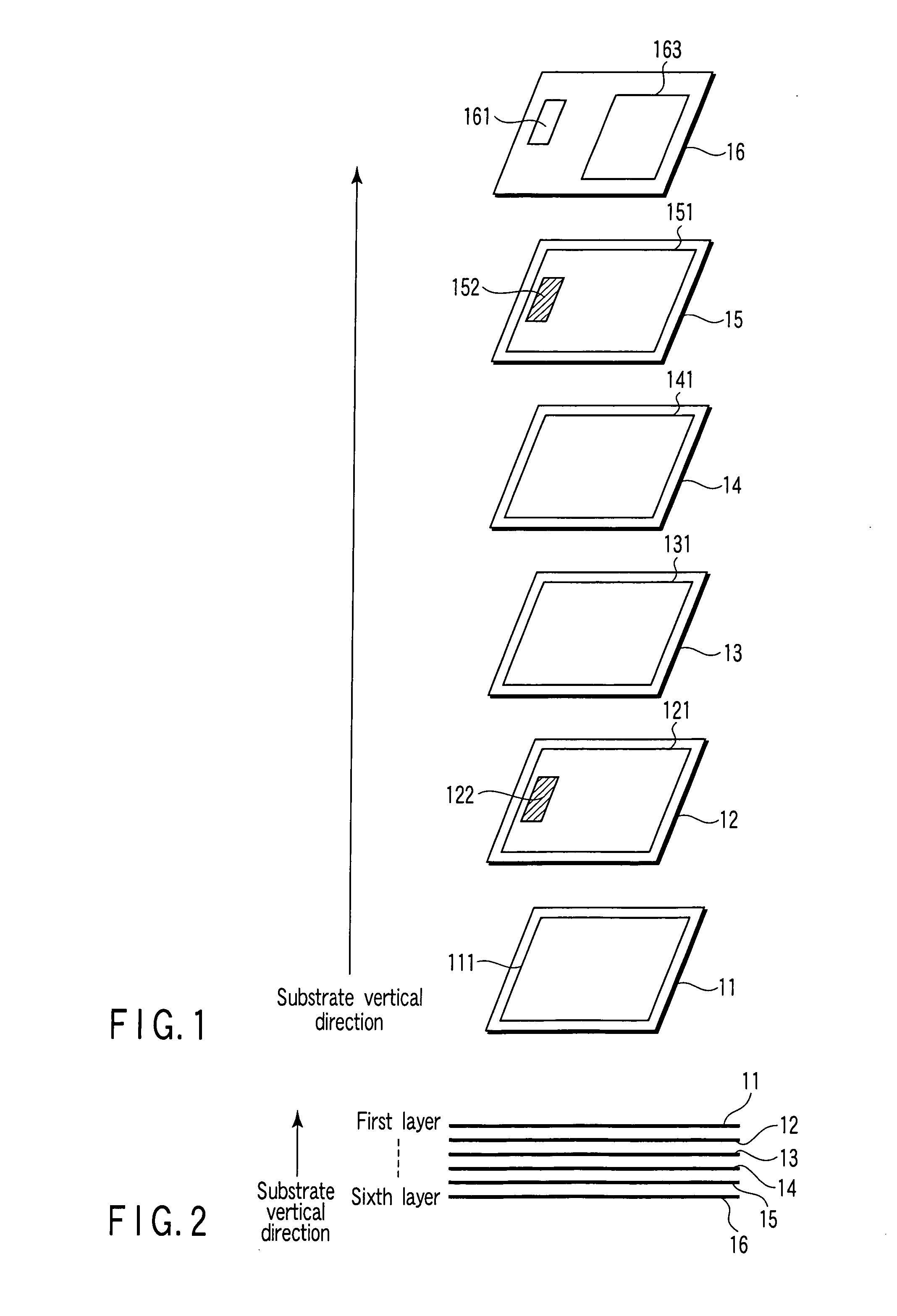
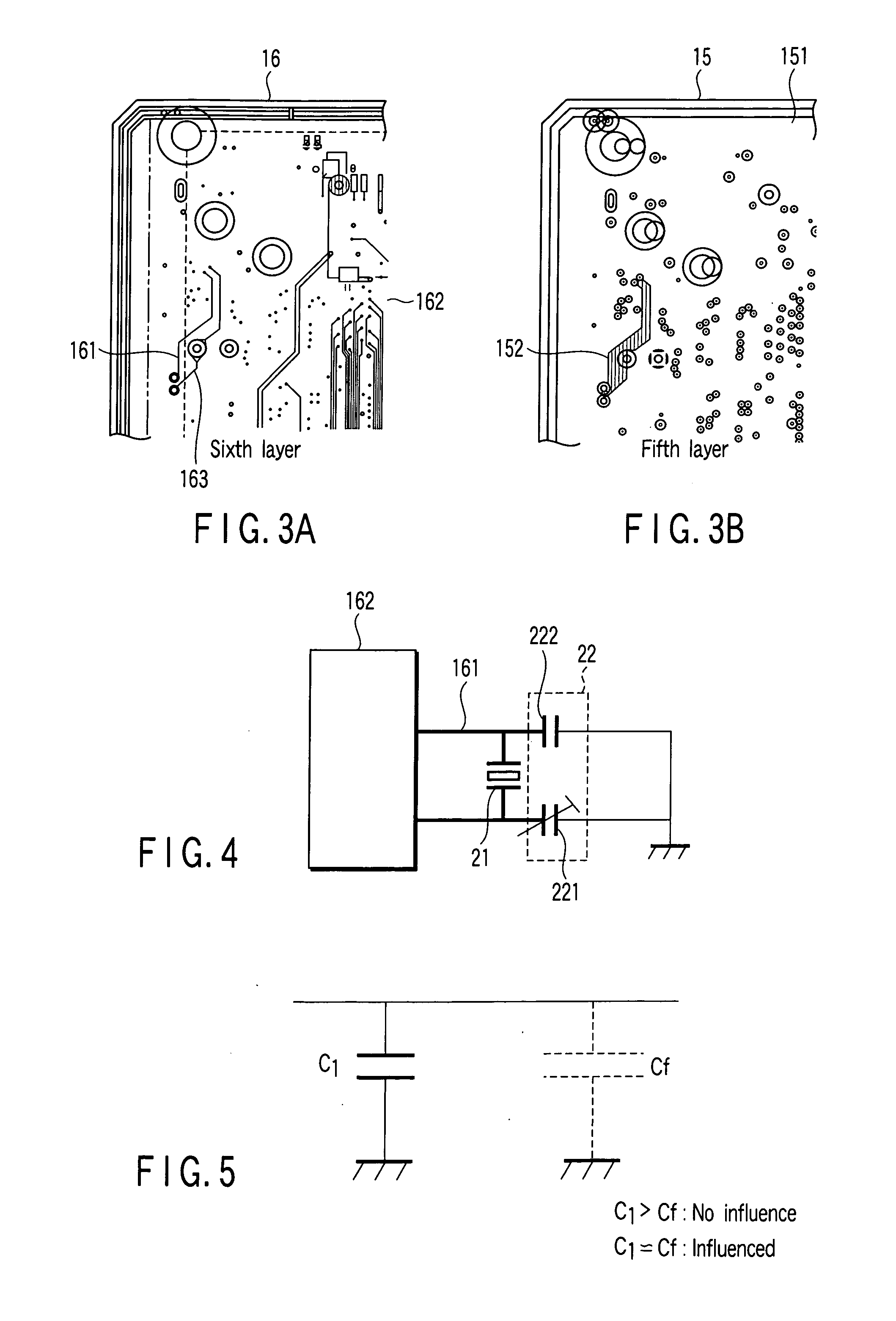
[0019] Various embodiments according to the invention will be described hereinafter with reference to the accompanying drawings. In general, according to one embodiment of the invention, a printed circuit board for a real-time clock IC comprising: a plurality of wiring layers sequentially laminated to form one substrata and including at least one layer which forms an oscillator circuit pattern having a crystal oscillator generating a reference signal and an oscillation stabilizing portion which stabilizes and oscillates the reference signal and adjusts the oscillation frequency to a target frequency, and a power supply layer or ground layer arranged in at least one of a position between the plurality of wiring layers and a position on one of front and rear surfaces of the substrata, and obtained by forming a power supply circuit pattern which supplies electric power to a circuit on the substrata and removing a portion of a power supply circuit pattern which has width not smaller tha...


PUM


Abstract

According to one embodiment, a printed circuit board for a real-time clock IC includes a plurality of wiring layers sequentially laminated to form one substrata and including at least one layer which forms an oscillator circuit pattern having a crystal oscillator generating a reference signal and an oscillation stabilizing portion which stabilizes and oscillates the reference signal and adjusts the oscillation frequency to a target frequency, and a power supply layer arranged in at least one of a position between the plurality of wiring layers and front and rear surfaces of the substrate, and forming a power supply circuit pattern which supplies electric power to a circuit on the substrate and removing a portion of the power supply circuit pattern which has width not smaller than width of the oscillator circuit pattern in a portion of the power supply circuit pattern which overlaps with the oscillator circuit pattern.

Description

CROSS-REFERENCE TO RELATED APPLICATIONS [0001] This application is based upon and claims the benefit of priority from Japanese Patent Application No. 2005-243217, filed Aug. 24, 2005, the entire contents of which are incorporated herein by reference. BACKGROUND [0002] 1. Field [0003] One embodiment of the invention relates to a printed circuit board for a real-time clock IC used in an electronic equipment such as a key-telephone equipment, for example, and a manufacturing method for the printed circuit board for the real-time clock IC. [0004] 2. Description of the Related Art [0005] Generally, a real time clock IC is used in an electronic equipment such as a key-telephone equipment to realize a real-time clock function. An oscillation frequency of 32.768 KHz is generally used in the real time clock IC and a tuning fork type crystal is used as a crystal oscillator which oscillates at the above frequency. [0006] In the above electronic equipment, the specification of an error of ±1 mi...

Claims


Application Information

Patent Timeline
Patent Type & Authority Applications(United States)
IPC IPC(8): G01R31/26
CPCH05K1/0224H05K1/0243H05K1/025H05K1/0253H05K2201/10196H05K2201/093H05K2201/0969H05K2201/10015H05K2201/10075H05K1/0298
Inventor FUNATO, YASUO
Owner KK TOSHIBA
Features
  • R&D
  • Intellectual Property
  • Life Sciences
  • Materials
  • Tech Scout
  • Unparalleled Data Quality
  • Higher Quality Content
  • 60% Fewer Hallucinations
Learn More