Supercharge Your Innovation With Domain-Expert AI Agents!

Dual wall exhaust manifold and method of making same

a dual-wall exhaust and manifold technology, applied in the field of dual-wall exhaust manifolds, can solve the problems of discoloration of the tubes, high-performance engines that generate extremely hot gas emissions, and the exhaust manifold or pipe is heated to increasingly high temperatures by hot emissions, so as to facilitate manufacture and assembly

Inactive Publication Date: 2007-08-09
METALDYNE TUBULAR COMPONENTS
View PDF13 Cites 7 Cited by
  • Summary
  • Abstract
  • Description
  • Claims
  • Application Information

AI Technical Summary

Benefits of technology

[0008] A dual wall exhaust manifold assembly is provided. The manifold has an outer shell and an inner shell spaced apart to allow for an air gap between the shells. To ease in manufacture and assembly, the inlet flange and the outlet flange have counterbores. The counterbore of the outlet flange aids in spacing the inner shell and the outer shell. The inner shell is connected to the outlet flange with a slip fit joint. The counterbore of the outlet flange provides an area to weld the outer shell to the outlet flange. The counterbore of the inlet flange allows space for welding the inner shell to the inlet flange. Advantageously, the manifold assembly of the present invention eliminates components typically required for manufacture of a dual wall exhaust manifold, such as stub tubes and spacers.

Problems solved by technology

Many modern high performance engines generate extremely hot gas emissions.
As these emissions are expelled from the engine and pass through the exhaust manifold, the hot emissions heat the exhaust manifold or pipes to increasingly high temperatures.
Such high temperatures cause the temperature of the tubes to elevate resulting in discoloration of the tubes.
However, use of stub tubes, spacers and the related labor associated with these components is costly.
Furthermore, manufacturing costs of a manifold assembly can be significant, and a continual need in the industry is to reduce these manufacturing costs.

Method used


Image

  • Dual wall exhaust manifold and method of making same
  • Dual wall exhaust manifold and method of making same
  • Dual wall exhaust manifold and method of making same

Examples


Embodiment Construction

[0016] Although the preferred embodiment of the invention has been illustrated in the accompanying drawings and described in the subsequent detailed description, it is to be understood that the invention is not to be limited to just the preferred embodiment disclosed, but that the invention described herein is capable of numerous rearrangements, modifications and substitutions without departing from the scope of the claims as appended hereafter.

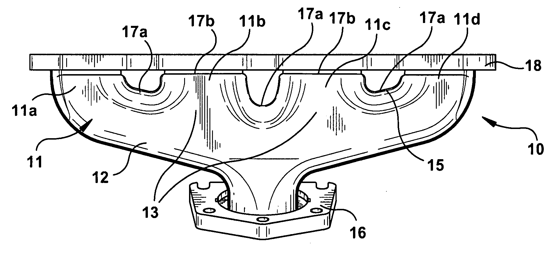
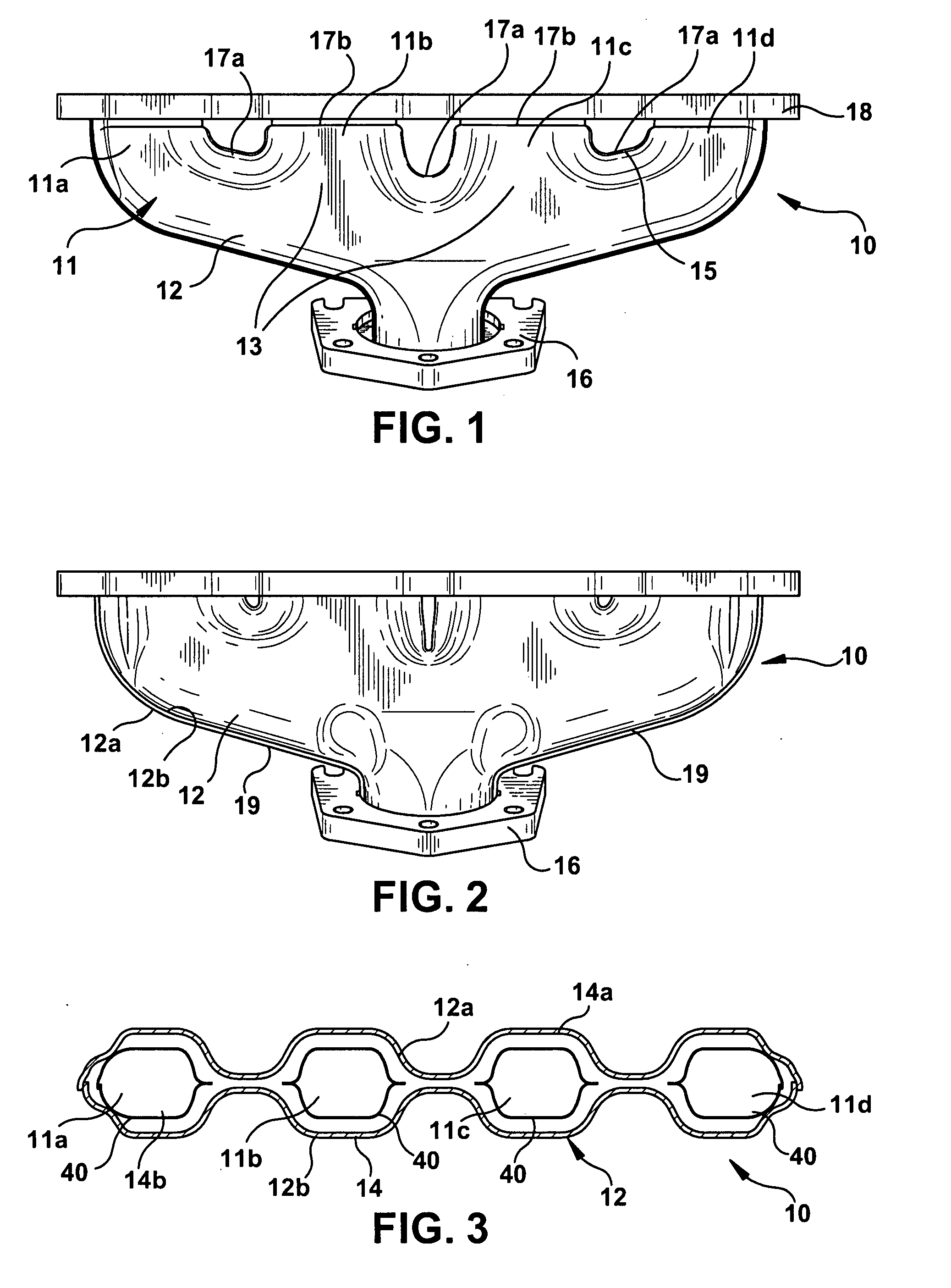
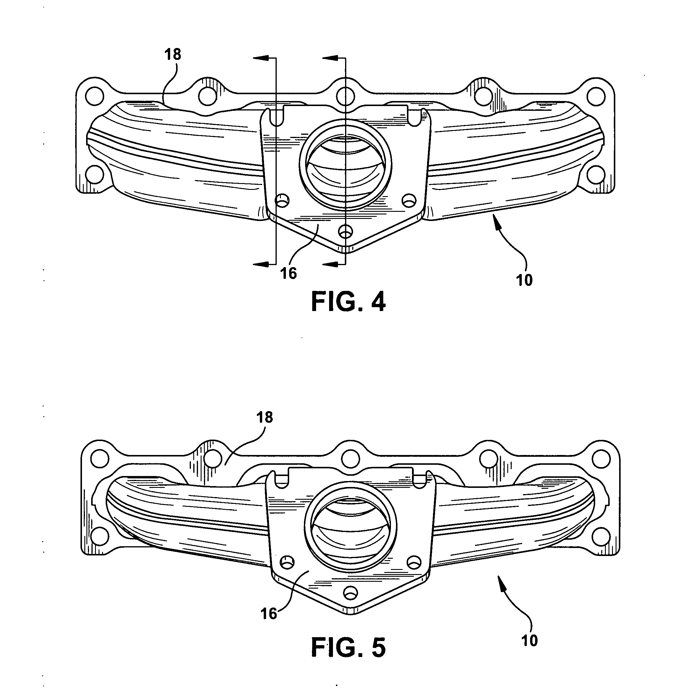
[0017] Referring to the drawings, a dual-walled exhaust manifold 10 having a body or log 11 is provided. The body 11 includes an outer shell 12 and an inner shell 14 connected to an outlet flange 16 and an inlet flange 18. The body 9 of the manifold 10 is in fluid communication with each of several runners 11a-11d, shown in the drawings as four in number. The illustrated manifold 10 can, for example, have any number of runners for any number of cylinders of an engine. For example, the manifold 10 can be used in a V-8 engine where the manifol...


PUM


Abstract

The present invention provides an improved dual-wall exhaust manifold assembly. The assembly has inner shells welded together and welded to an inlet flange. Outer shells are inserted into a counterbore of the inlet flange. An outlet flange is slid over the inner shell. The inner shell and the outer shell are inserted into the counterbore of the outlet flange. The outer shells are welded together and to the outlet and inlet flanges. The inlet counterbore and the outlet flange counterbore separate the inner and outer shells.

Description

RELATED APPLICATIONS [0001] This non-provisional application claims the benefit of U.S. Provisional Patent Application No. 60 / 756,238, entitled “DUAL WALL EXHAUST MANIFOLD,” filed Jan. 3, 2005, which is hereby incorporated by reference in its entirety.FIELD OF ART [0002] The present invention relates generally to exhaust manifolds, and more specifically, to dual-wall exhaust manifolds for use with internal combustion engines. BACKGROUND OF THE INVENTION [0003] Many modern high performance engines generate extremely hot gas emissions. As these emissions are expelled from the engine and pass through the exhaust manifold, the hot emissions heat the exhaust manifold or pipes to increasingly high temperatures. Such high temperatures cause the temperature of the tubes to elevate resulting in discoloration of the tubes. As such, some component designs utilize a dual wall construction that utilizes an air gap between the inner and outer tubes. Known dual wall manifolds utilize spacers and s...

Claims


Application Information

Patent Timeline
Patent Type & Authority Applications(United States)
IPC IPC(8): F01N5/02F01N7/10F01N3/02F01N13/10
CPCF01N13/102F01N13/143F01N2450/22F01N13/1861F01N13/1872F01N13/1811
Inventor KENYON, PAUL W.SCHMIDT, MICHAEL P.
Owner METALDYNE TUBULAR COMPONENTS
Features
  • R&D
  • Intellectual Property
  • Life Sciences
  • Materials
  • Tech Scout
  • Unparalleled Data Quality
  • Higher Quality Content
  • 60% Fewer Hallucinations
Learn More